Volkswagen Golf / Golf GTI / Golf Variant. Manual - part 945


  Index      Volkswagen     Volkswagen Golf / Golf GTI / Golf Variant - service repair manual 2013 year


Search            copyright infringement  


Content   ..  943  944  945  946   ..


Volkswagen Golf / Golf GTI / Golf Variant. Manual - part 945


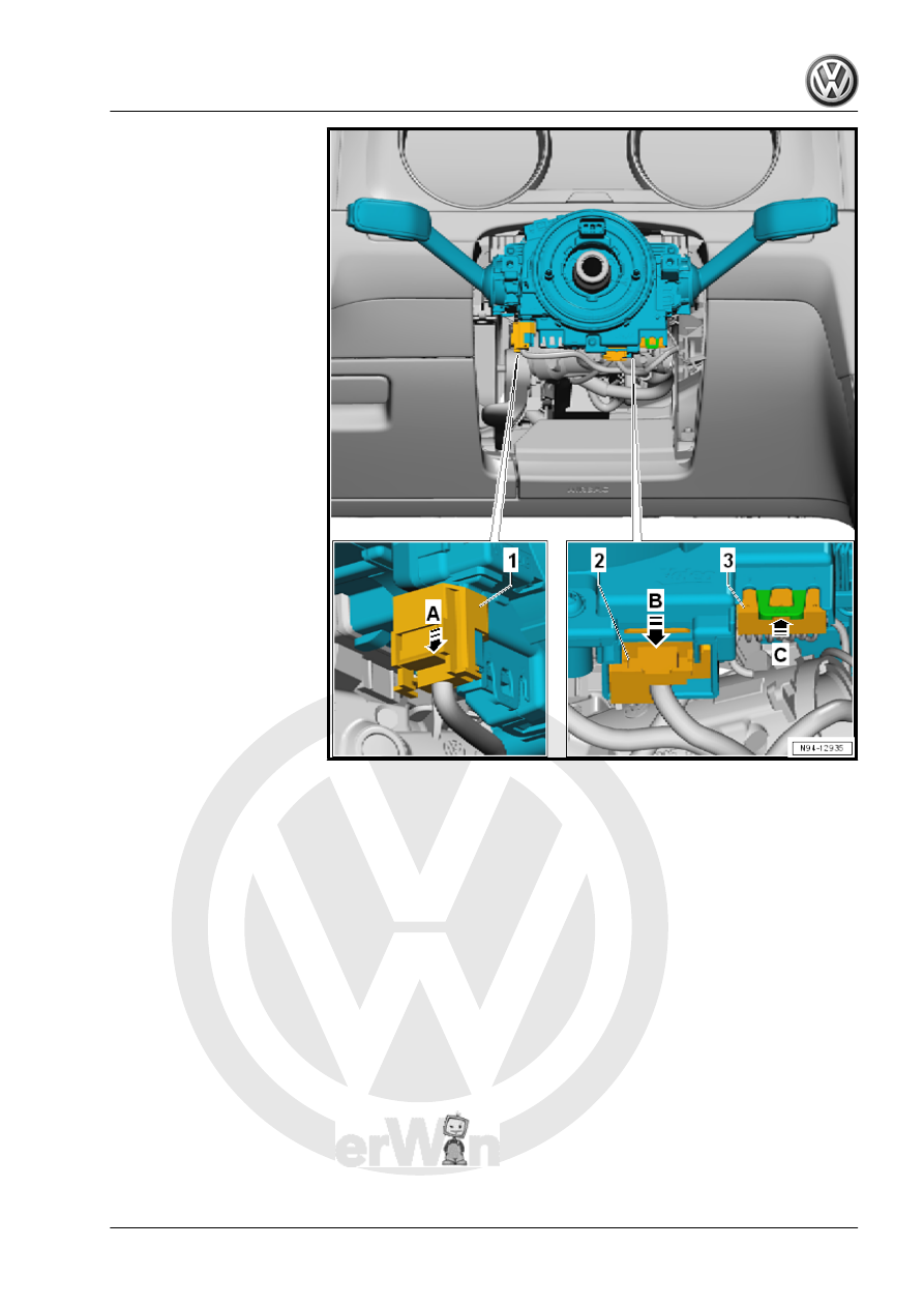
– Disconnect the connector -1-.
– Remove the connector lock in the direction of the -arrow B-

and press down.

– Disconnect the connector -2-.
– Push the connector lock in the direction of the -arrow C- and

disconnect the connector -3-.

– Push the release -1- on both sides in the direction of the

-arrow A-.

– Slightly remove the steering column switch module -2-.
– Push the release -3- in the direction of the -arrow B-.
– Remove the steering column switch module -2-.
Installing
Install in the reverse order of removal while paying attention to

the following:
– The following must be checked on the Steering Column Elec‐

tronics Control Module - J527- -3- before sliding on the steer‐

ing column switch module:

♦ The “arrows” -1- must align.
♦ The spiral spring -2- must be seen in the window between the

“arrows” -4-.

8.6

Steering Column Electronics Control

Module - J527- , Removing and Instal‐

ling

⇒ “8.6.1  Steering Column Electronics Control Module J527 , Re‐

moving and Installing, Kostal”, page 187
⇒ “8.6.2  Steering Column Electronics Control Module J527 , Re‐

moving and Installing, Valeo”, page 189

8.6.1

Steering Column Electronics Control

Module - J527- , Removing and Instal‐

ling, Kostal

The Airbag Spiral Spring/Return Spring with Slip Ring - F138- is

integrated into the Steering Column Electronics Control Module -

J527- .
If the control module is being replaced, use the Vehicle Diagnostic

Tester and select the “Replacing” function for the respective con‐

trol module in “Guided Fault Finding”.
Removing
– Position the front wheels straight-ahead. The steering wheel

is located in the neutral position.

– Position the steering wheel as far back as possible. Use the

entire adjustment range of the steering column adjustment for

this.

– Remove the steering wheel. Refer to ⇒  Suspension, Wheels,

Steering; Rep. Gr.  48 ; Steering Wheel; Steering Wheel, Re‐

moving and Installing .

– Remove the lower steering column trim panel. Refer to ⇒  Body

Interior; Rep. Gr.  68 ; Storage Compartments and Covers;

Lower Steering Column Trim Panel, Removing and Installing .

WARNING

Risk of destroying electronic components with static discharge.

♦ Before disconnecting the connector, discharge static elec‐

tricity from your body by touching a grounded vehicle

component such as the door striker pin.

– Push the connector lock in the direction of the -arrow A- and

disconnect the connector -1-.

– Push the connector lock in the direction of the -arrow B- and

disconnect the connector -2-.

– Push the connector lock in the direction of the -arrow C- and

disconnect the connector -3-.

– Remove the connector lock in the direction of the -arrow D-

and press down.

– Disconnect the connector -4-.
– Push the connector lock in the direction of the -arrow E- and

disconnect the connector -5-.

– Remove the connector lock in the direction of the -arrow F-

and press down.

– Disconnect the connector -6-.
– Remove the bolt -1-.
– Release the mounting tabs in the direction of the

-arrows A and B-.


Content   ..  943  944  945  946   ..