Volkswagen Golf / Golf GTI / Golf Variant. Manual - part 944


  Index      Volkswagen     Volkswagen Golf / Golf GTI / Golf Variant - service repair manual 2013 year


Search            copyright infringement  


Content   ..  942  943  944  945   ..


Volkswagen Golf / Golf GTI / Golf Variant. Manual - part 944


– Release the retainer in direction of -arrow A- and remove the

Ignition Switch Key Lock Solenoid - N376- -2- from the steering

lock housing -1- in direction of -arrow B-.

Installing
Install in reverse order of removal.

8.4

Ignition/Starter Switch, Removing and

Installing

Removing
– Turn off the ignition and all electrical equipment.
– Remove the ignition key, if equipped.
– Remove the lower steering column trim panel. Refer to ⇒  Body

Interior; Rep. Gr.  68 ; Storage Compartments and Covers;

Lower Steering Column Trim Panel, Removing and Installing .

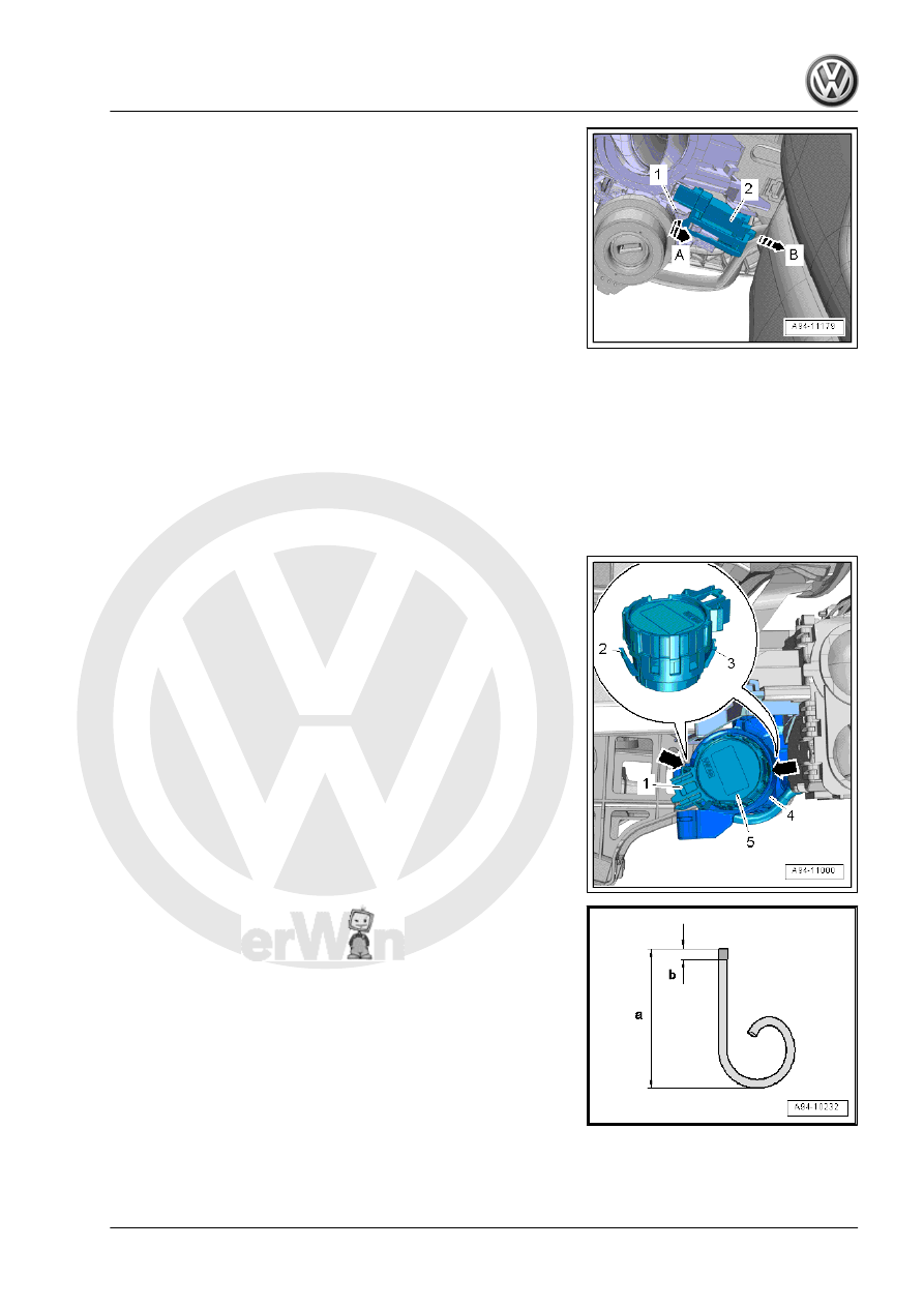
– Release and disconnect the connector -1-.
– Release the clips -2 and 3- by inserting a suitable screwdriver

in the openings -arrows- in the steering lock housing -4-.

If the procedure is not possible because there is not enough

space, create a tool from two wire hooks as follows.
– Bend the one end of a welding wire to form a 1 mm eye.
– Cut the welding wire down to the length -a-.
♦ Dimension -a- = approximately 50 mm
– File the end of the wire hook into a point.
♦ Dimension -b- = 5 mm

– Remove the Ignition/Starter Switch - D- -5- from the steering

lock housing. The jeweler's screwdriver or wire hooks must

remain inserted.

Installing
Install in the reverse order of removal while paying attention to

the following:
– Insert the Ignition/Starter Switch - D- into the steering lock

housing until it audibly engages.

8.5

Steering Column Switch Module, Re‐

moving and Installing

⇒ “8.5.1 Steering Column Switch Module, Removing and Instal‐

ling, Kostal”, page 182
⇒ “8.5.2 Steering Column Switch Module, Removing and Instal‐

ling, Valeo”, page 184

8.5.1

Steering Column Switch Module, Re‐

moving and Installing, Kostal

Removing
– Position the steering wheel as far back as possible. Use the

entire adjustment range of the steering column adjustment for

this.

– Remove the steering wheel. Refer to ⇒  Suspension, Wheels,

Steering; Rep. Gr.  48 ; Steering Wheel; Steering Wheel, Re‐

moving and Installing .

– Remove the lower steering column trim panel. Refer to ⇒  Body

Interior; Rep. Gr.  68 ; Storage Compartments and Covers;

Lower Steering Column Trim Panel, Removing and Installing .

WARNING

Risk of destroying electronic components with static discharge.

♦ Before disconnecting the connector, discharge static elec‐

tricity from your body by touching a grounded vehicle

component such as the door striker pin.

– Remove the connector lock in the direction of the -arrow A-

and press down.

– Disconnect the connector -1-.
– Remove the connector lock in the direction of the -arrow B-

and press down.

– Disconnect the connector -2-.
– Push the connector lock in the direction of the -arrow C- and

disconnect the connector -3-.

– Remove the bolt -2- on the bottom.
– Remove the steering column switch module -1-.
Installing
Install in the reverse order of removal while paying attention to

the following:

– The following must be checked on the Steering Column Elec‐

tronics Control Module - J527- -3- before sliding on the steer‐

ing column switch module:

♦ The “arrows” -1- must align.
♦ The spiral spring -2- must be seen in the window between the

“arrows” -4-.

Tightening Specifications
♦ Refer to

⇒ “8.1 Overview - Steering Column Switch Module”,

page 176

8.5.2

Steering Column Switch Module, Re‐

moving and Installing, Valeo

Removing
– Position the steering wheel as far back as possible. Use the

entire adjustment range of the steering column adjustment for

this.

– Remove the steering wheel. Refer to ⇒  Suspension, Wheels,

Steering; Rep. Gr.  48 ; Steering Wheel; Steering Wheel, Re‐

moving and Installing .

– Remove the lower steering column trim panel. Refer to ⇒  Body

Interior; Rep. Gr.  68 ; Storage Compartments and Covers;

Lower Steering Column Trim Panel, Removing and Installing .

WARNING

Risk of destroying electronic components with static discharge.

♦ Before disconnecting the connector, discharge static elec‐

tricity from your body by touching a grounded vehicle

component such as the door striker pin.

– Remove the connector lock in the direction of the -arrow A-

and press down.


Content   ..  942  943  944  945   ..