Volkswagen Golf / Golf GTI / Golf Variant. Manual - part 904


  Index      Volkswagen     Volkswagen Golf / Golf GTI / Golf Variant - service repair manual 2013 year


Search            copyright infringement  


Content   ..  902  903  904  905   ..


Volkswagen Golf / Golf GTI / Golf Variant. Manual - part 904


Removing
– Disconnect the Battery - A- . Refer to

⇒ “1.3 Battery, Disconnecting and Connecting”, page 9

 .

– Remove the ribbed belt. Refer to ⇒  Rep. Gr.  13 ; Cylinder

Block, Belt Pulley Side; Ribbed Belt, Removing and Installing .

– Remove the ribbed belt tensioner. Refer to ⇒  Rep. Gr.  13 ;

Cylinder Block, Belt Pulley Side; Ribbed Belt Tensioner, Re‐

moving and Installing .

Vehicles with A/C System

Caution

Danger of damaging the A/C compressor, the refrigerant line

and hoses.

♦ Do not stretch, bend or kink the refrigerant lines and ho‐

ses.

– Remove the A/C compressor from the bracket. Refer to ⇒ 

Heating and Air Conditioning; Rep. Gr.  87 ; A/C Compressor;

A/C Compressor, Removing and Installing on Bracket .

– Secure the A/C compressor on the lock carrier so that the re‐

frigerant lines are not under tension.

Continuation for All Vehicles
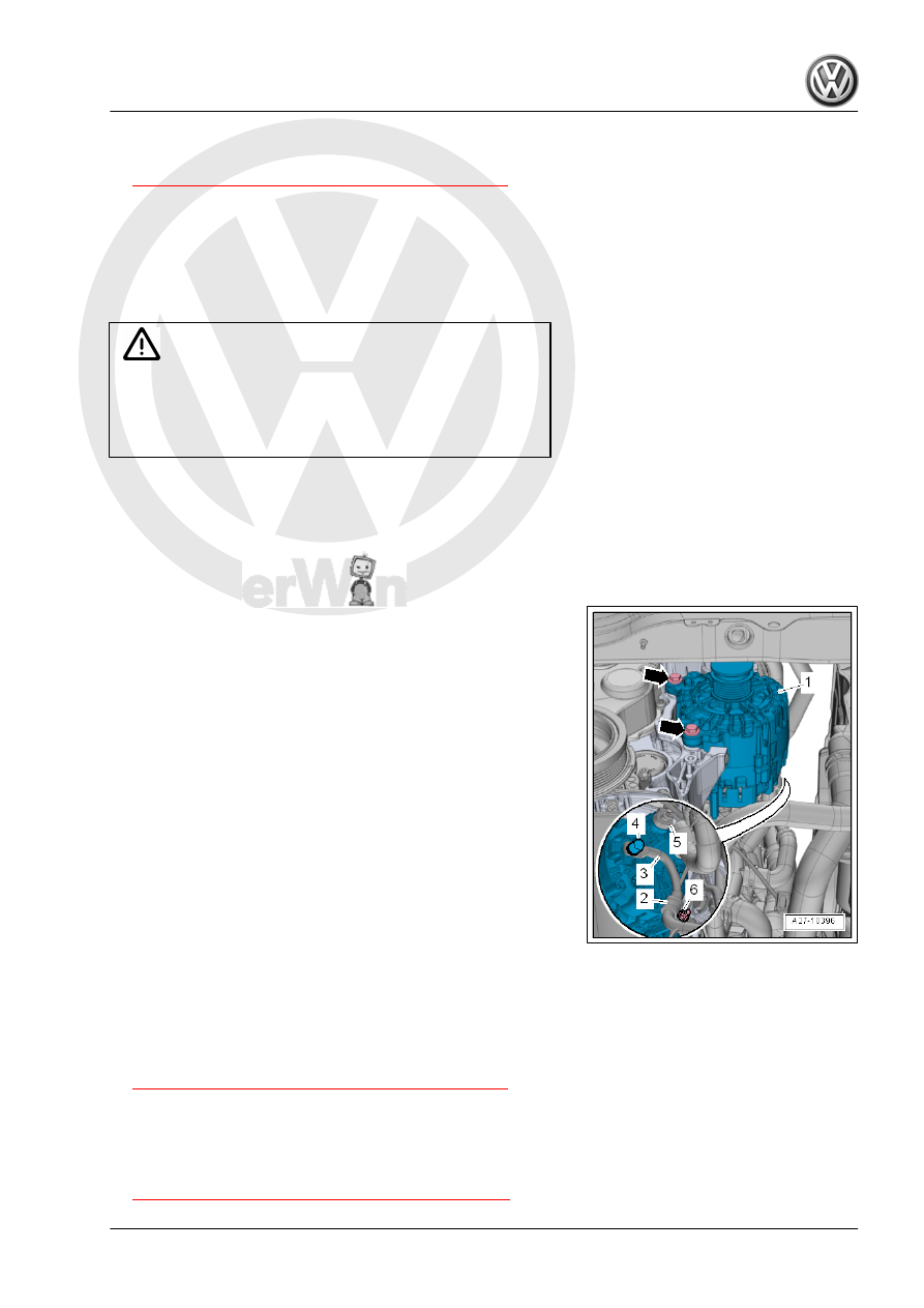
– Remove the bolts -arrows-.
If the Generator - C- -1- sticks in the bracket, install screw again

down as far as the last two turns.
Carefully strike on bolt heads using flat side of hammer - doing

this loosens the generator mount bushings.
– Remove the Generator - C- -1- with the wires still attached

from the bracket.

– Disconnect the connector -5-.
– Pry off the cap -4-.
– Remove the nut and remove the terminal 30/B+ -3-.
– Remove the nut -6- and remove the wire clamp -2-.
– Remove the Generator - C- -1- downward and to the right.
Installing
Install in the reverse order of removal while paying attention to

the following:
– Move the bolt sleeves slightly to the rear to make it easier to

install the Generator - C- .

Tight bushings for generator mount must be made smooth-run‐

ning, otherwise clamping force of bushing is too little despite

correct torque.
– Connect the Battery - A- . Refer to

⇒ “1.3 Battery, Disconnecting and Connecting”, page 9

 .

– After completing work always start the engine and check the

belt routing.

Tightening Specifications
♦ Refer to

⇒ “2.1.2 Overview - Generator with Bushings”, page 14

2.3

Generator, Checking

– Check the Generator - C- using the Vehicle Diagnostic Tester .

2.4

Ribbed Belt Pulley, Removing and In‐

stalling

⇒ “2.4.1 Ribbed Belt Pulley without Freewheel, Removing and

Installing”, page 22
⇒ “2.4.2 Ribbed Belt Pulley with Freewheel, Removing and In‐

stalling, Bosch”, page 22
⇒ “2.4.3 Ribbed Belt Pulley with Freewheel, Removing and In‐

stalling, Valeo”, page 24
⇒ “2.4.4 Decoupling Belt Pulley with Freewheel, Removing and

Installing”, page 25

2.4.1

Ribbed Belt Pulley without Freewheel,

Removing and Installing

Special tools and workshop equipment required
♦ Generator Belt Socket - 3310-
♦ Torque Wrench 1332 40-200Nm - VAG1332-
Removing
– Remove the Generator - C- . Refer to

⇒ “2.2 Generator, Removing and Installing”, page 15

 .

– Secure the Generator - C- in a vise by the mounting points.
– Remove the ribbed belt pulley nut using -3310- from the gen‐

erator shaft.

– Remove the ribbed belt pulley from the generator shaft.
Installing
Install in the reverse order of removal while paying attention to

the following:

Tightening Specifications

Component

Tightening Specification

Ribbed belt pulley nut

65 Nm

2.4.2

Ribbed Belt Pulley with Freewheel, Re‐

moving and Installing, Bosch

Special tools and workshop equipment required
♦ Multi-Tooth Adapter - 3400-
♦ Torque Wrench 1332 40-200Nm - VAG1332-
Removing
– Remove the Generator - C- . Refer to

⇒ “2.2 Generator, Removing and Installing”, page 15

 .

– Secure the Generator - C- in a vise by the mounting points.

– Pry up the cap from the ribbed belt pulley.
– Install the -3400- with the wrench (SW 17) in the ribbed belt

pulley.

– Install the multi-point socket M10 -1- in the generator shaft.
– Hold the generator secure and loosen the ribbed belt pulley

with the wrench by turning left.

– Hold the ribbed belt pulley securely by hand.
– Turn the generator shaft until the ribbed belt pulley can be re‐

moved.

Installing
Install in the reverse order of removal while paying attention to

the following:
– Install the ribbed belt pulley by hand until stop on the generator

shaft.

The -VAG1332- must be rearranged for installing ribbed belt pul‐

ley as follows:

– Release the insert -1- and remove it from the handle part -2-.
– Turn the handle part -2- 180° and install the socket -1- again.
– Set the rotation direction of the -VAG1332- bit to the left.

– Install the multi-point socket M10 -1- in the generator shaft.
– Counterhold the -3400- with a wrench (SW 17).
– Tighten the ribbed belt pulley by turning the generator shaft to

the left using -VAG1332- .

Tightening Specifications

Component

Tightening Specification

Ribbed belt pulley nut

80 Nm

2.4.3

Ribbed Belt Pulley with Freewheel, Re‐

moving and Installing, Valeo

Special tools and workshop equipment required
♦ Multi-Tooth Adapter - 3400-
♦ Torque Wrench 1332 40-200Nm - VAG1332-
♦ Torx Key Socket Set - VAG1603A/1-
Removing
– Remove the Generator - C- . Refer to

⇒ “2.2 Generator, Removing and Installing”, page 15

 .

– Secure the Generator - C- in a vise by the mounting points.
– Pry up the cap from the ribbed belt pulley.
– Install the -3400- with the wrench (SW 17) in the ribbed belt

pulley.

– Install the -VAG1603A/1- in the generator shaft.
– Hold the generator secure and loosen the ribbed belt pulley

with the wrench by turning left.

– Hold the ribbed belt pulley securely by hand.
– Turn the generator shaft until the ribbed belt pulley can be re‐

moved.

Installing
Install in the reverse order of removal while paying attention to

the following:
– Install the ribbed belt pulley by hand until stop on the generator

shaft.

The -VAG1332- must be rearranged for installing ribbed belt pul‐

ley as follows:

– Release the insert -1- and remove it from the handle part -2-.
– Turn the handle part -2- 180° and install the socket -1- again.
– Set the rotation direction of the -VAG1332- bit to the left.


Content   ..  902  903  904  905   ..