Volkswagen Golf / Golf GTI / Golf Variant. Manual - part 874


  Index      Volkswagen     Volkswagen Golf / Golf GTI / Golf Variant - service repair manual 2013 year


Search            copyright infringement  


Content   ..  872  873  874  875   ..


Volkswagen Golf / Golf GTI / Golf Variant. Manual - part 874


Caution

This procedure contains mandatory replaceable parts. Refer

to component overview prior to starting procedure.

Mandatory Replacement Parts
♦ Nut - Control Arm to Front Level Control System Sensor
Removing
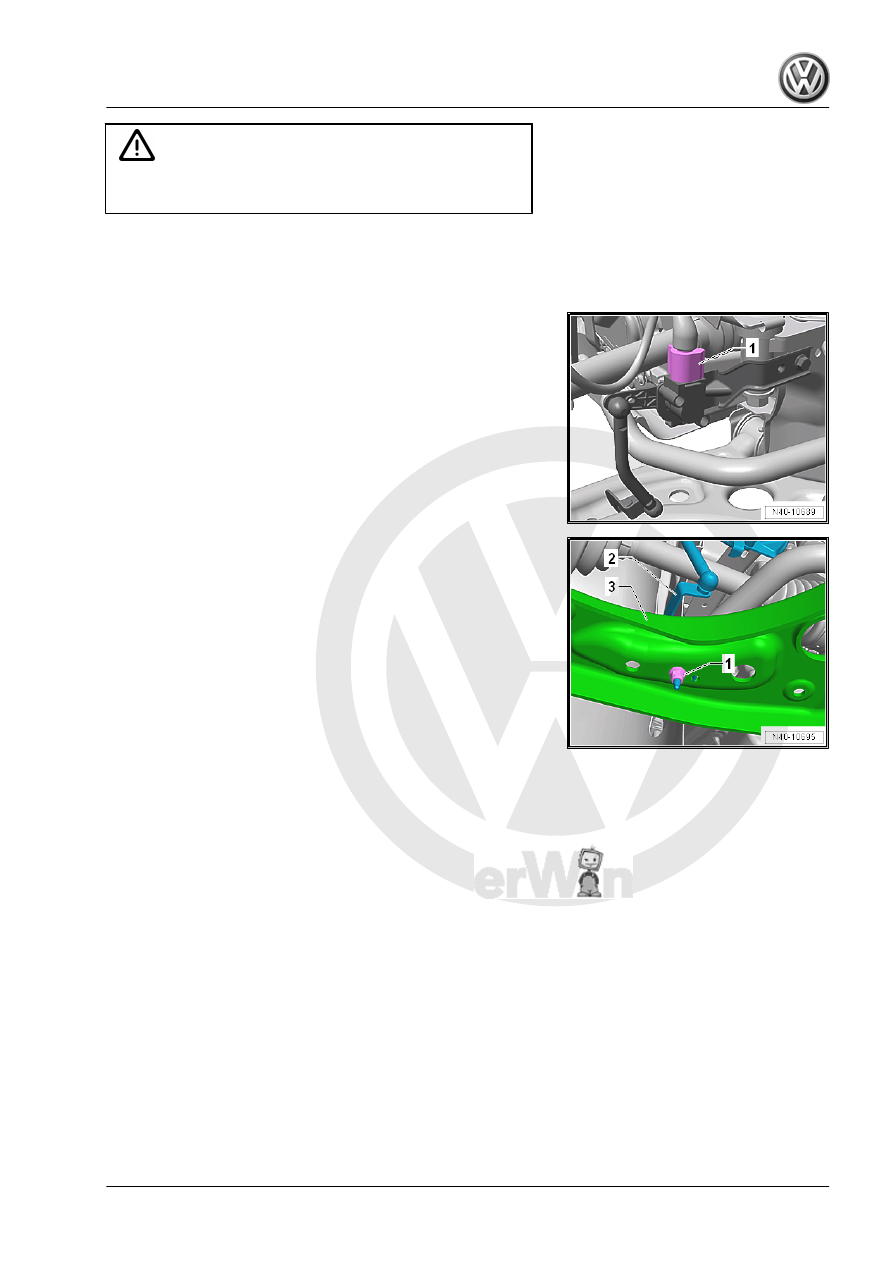
– Disconnect the connector -1- from the Left Front Level Control

System Sensor - G78- or Right Front Level Control Sensor -

G289- .

– Remove nut -1-.
– Remove the bracket -2- for the Left Front Level Control System

Sensor - G78- or Right Front Level Control Sensor - G289-

from the control arm -3-.

Pro

te

c

t

ed

  b

y

  co

p

y

rig

h

t. 

C

o

p

y

in

g

  fo

pr

iv

a

t

e

 o

r

 c

o

m

m

e

r

c

ia

p

u

rp

o

s

e

s

,

 i

n

 p

a

rt

o

r i

n

 w

h

o

le

is

 n

o

t

 p

e

r

m

it

t

e

d

 u

n

l

e

s

s

 a

ut

ho

r

i

s

ed

 b

y

 V

olk

sw

a

ge

n AG

.


V

olk

s

w

a

g

en

 AG do

es 

n

ot g

uar

ante

e

 or a

c

c

ep

t

 a

ny


li

a

b

i

li

t

y

 w

ith

 r

e

s

p

e

c

t

 t

o


th

e

 c

o

rr

e

c

t

n

e

s

s


o

f

in

fo

r

m

a

tio

n

 in

 th

is

 d

o

c

um

en

t.

C

o

py

rig

ht b

y


V

olk

sw

a

ge

n


A

G.

– Remove the bolt -1-.
– Remove the Left Front Level Control System Sensor - G78- or

Right Front Level Control Sensor - G289- .

Installing
Installation is the reverse of removal, with special attention to the

following:

Note

The level control system sensor lever must point toward vehi‐

cle exterior.

The thread on the level control system sensor must be instal‐

led in the outer hole in the control arm. The tab on the level

control system sensor must fit into the inner hole to assure that

the installation position is correct.

• Perform the basic setting for the wheel damping electronics.

Refer to Vehicle Diagnostic Tester .

• If the control position was reprogrammed and if the vehicle has

lane assist, then the front camera for the driver assistance

systems must be calibrated.

• Perform the basic setting of the headlamps. Refer to ⇒  Elec‐

trical Equipment; Rep. Gr.  94 ; Headlamp; Headlamp, Adjust‐

ing .

Tightening Specifications
♦ Refer to

⇒ “2.1 Overview - Front Level Control System Sensor”,

page 277

2.4

Left/Right Rear Level Control System

Sensor -G76- / -G77- , Removing and

Installing

⇒ “2.4.1  Left Rear Level Control System Sensor G76 , Removing

and Installing, Torsion Beam Axle”, page 282
⇒ “2.4.2  Left Rear Level Control System Sensors G76 , Remov‐

ing and Installing, Multi-Link Suspension”, page 283
⇒ “2.4.3  Left Rear Level Control System Sensors G76 , Remov‐

ing and Installing, Multi-Link Suspension, AWD”, page 284

2.4.1

Left Rear Level Control System Sensor

- G76- , Removing and Installing, Tor‐

sion Beam Axle

Special tools and workshop equipment required
♦ Torque Wrench 1410 - VAG1410-
♦ Vehicle Diagnostic Tester

Removing
– Disconnect the connector -1-.
– Remove the bolts -2 and 4-.
– Remove the Left Rear Level Control System Sensor - G76-

-3-.

Installing
Installation is the reverse of removal, with special attention to the

following:

Note

The Left Rear Level Control System Sensor - G76- lever must

face opposite the direction of travel.

• Perform the basic setting for the wheel damping electronics.

Refer to Vehicle Diagnostic Tester .

• Perform the basic setting of the headlamps. Refer to ⇒  Elec‐

trical Equipment; Rep. Gr.  94 ; Headlamp; Headlamp, Adjust‐

ing .

Tightening Specifications
♦ Refer to

⇒ “2.2.1 Overview - Rear Level Control System Sensor, Tor‐

sion Beam Axle”, page 278

2.4.2

Left Rear Level Control System Sensors

- G76- , Removing and Installing, Multi-

Link Suspension

Special tools and workshop equipment required
♦ Torque Wrench 1410 - VAG1410-
♦ Vehicle Diagnostic Tester
Removing
– Disconnect the connector -1-.
– Remove the bolts -2 and 3-.
– Remove the Left Rear Level Control System Sensor - G76-

-4-.

Installing
Installation is the reverse of removal, with special attention to the

following:
The level control system sensor lever must point toward vehicle

exterior.
• Perform the basic setting for the wheel damping electronics.

Refer to Vehicle Diagnostic Tester .

• Perform the basic setting of the headlamps. Refer to ⇒  Elec‐

trical Equipment; Rep. Gr.  94 ; Headlamp; Headlamp, Adjust‐

ing .

Tightening Specifications
♦ Refer to

⇒ “2.2.2 Overview - Rear Level Control System Sensor, Multi-

Link Suspension”, page 279

2.4.3

Left Rear Level Control System Sensors

- G76- , Removing and Installing, Multi-

Link Suspension, AWD

Special tools and workshop equipment required
♦ Torque Wrench 1410 - VAG1410-
♦ Vehicle Diagnostic Tester
Removing
– Disconnect the connector -1-.
– Remove the bolts -2 and 3-.
– Remove the Left Rear Level Control System Sensor - G76-

-4-.

Installing
Installation is the reverse of removal, with special attention to the

following:
The level control system sensor lever must point toward vehicle

exterior.
• Perform the basic setting for the wheel damping electronics.

Refer to Vehicle Diagnostic Tester .

• Perform the basic setting of the headlamps. Refer to ⇒  Elec‐

trical Equipment; Rep. Gr.  94 ; Headlamp; Headlamp, Adjust‐

ing .

Tightening Specifications
♦ Refer to

⇒ “2.2.2 Overview - Rear Level Control System Sensor, Multi-

Link Suspension”, page 279


Content   ..  872  873  874  875   ..