Volkswagen Golf / Golf GTI / Golf Variant. Manual - part 866


  Index      Volkswagen     Volkswagen Golf / Golf GTI / Golf Variant - service repair manual 2013 year


Search            copyright infringement  


Content   ..  864  865  866  867   ..


Volkswagen Golf / Golf GTI / Golf Variant. Manual - part 866


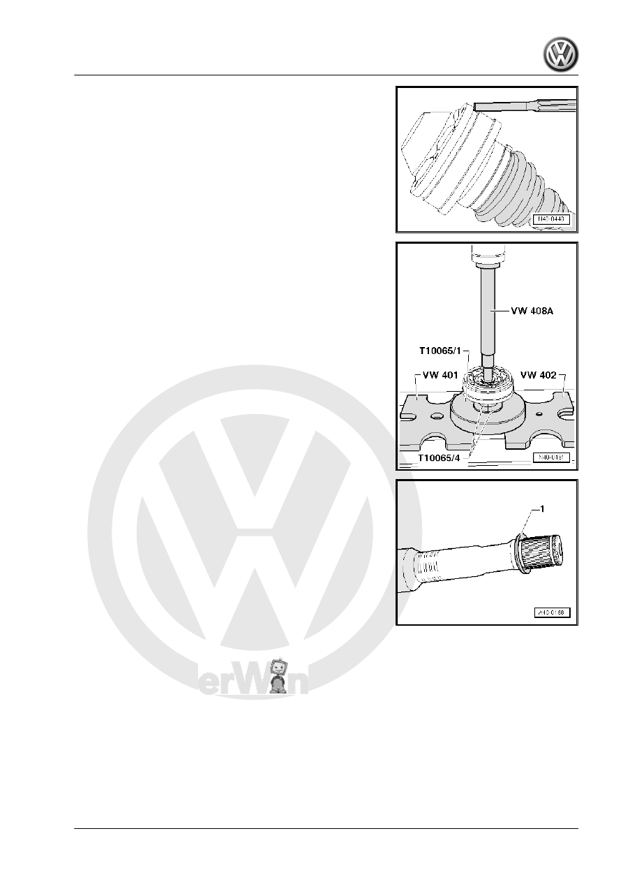
Drive Off Cover for Inner Joint

Removing the Inner CV Joint
– Press off CV from joint using drift.
– Remove the circlip.
– Remove both clamps, and push the CV boot toward outer joint.
Assembling

Installed Location of the Plate Spring on Inner Joint
1 - Plate Spring

Pressing On Inner CV Joint

Note

Chamfer on inner diameter of ball hub (splines) must face the

contact shoulder on the drive axle.

– Press on joint until stop.
– Install the circlip.

– Align new cover with bolts -arrows- to bolt holes.

Note

It must be aligned exactly because it cannot be aligned after driv‐

ing on.

– Drive cover on with a plastic hammer.

Tightening Clamping Sleeve on Outer Joint
– Position Clamping Pliers - VAG1682A- as shown in illustration.

When doing this, make sure that edges of clamping pliers are

seated in corners -arrows B- of clamp.

– Tension clamp by turning spindle with a torque wrench (do not

tilt clamp tool).

Note

The hard material of the joint boot (compared to rubber) makes

it necessary to use a stainless steel hose clamp. It is only pos‐

sible to tighten the hose clamp with Clamping Pliers -

VAG1682A- .

Tightening specification: 25 Nm.

Use torque wrench -C- with adjustment range 5 to 50 Nm (for

example Torque Wrench 5-50Nm - VAG1331- ).

Be sure thread of spindle -A- of clamp tool moves freely.

Grease with MOS 2 grease if necessary.

If the thread is tight, for example, dirty, the required tensioning

force for the hose clamp will not be achieved in spite of correct

torque specification settings.

Tensioning Clamp on Small Diameter

8.5

Outer CV Joint, Checking

The joint is to be disassembled if badly contaminated to replace

the grease, or when the ball contact surfaces show wear or dam‐

age.
Removing
– Before disassembling mark ball hub position in relation to the

ball cage and housing with an electro-writer or oil stone

-arrow-.

– Tilt ball hub and ball cage and remove balls one after another.

– Turn cage until the two rectangular windows -arrow- are

aligned with the joint housing.

– Lift out cage with hub.

– Swing a hub segment in a cage window.
– Fold hub out from cage.

Note

The six balls of each joint belong to one tolerance group.

Check stub axle, hub, cage and balls for small depressions

(pitting build-up) and chafing.

Excessive circumferential backlash in joint makes itself no‐

ticed via tip-in shock, in such cases joint should be replaced.

Flattening and running marks of balls are no reason to replace

joint.

Installing
Install in reverse order of removal. Note the following:
– Press half of the grease amount from the repair kit into the joint

housing.

– Insert cage with hub into joint body.

Note

Cage must be installed laterally correct.

– Press in opposing balls in sequence, during this, previous po‐

sition of ball hub to ball cage and to joint body must be

established again.

– Install new circlip in shaft.
– Distribute remaining grease in the joint boot.

8.6

Inner CV Joint, Checking

The joint is to be disassembled if badly contaminated to replace

the grease, or when the ball contact surfaces show wear or dam‐

age.

Note

Ball hub and joint piece are paired. Before removing, mark in re‐

lation to each other using a waterproof felt-tip pen.

Removing
– Swivel the ball hub and ball cage.
– Remove the joint in the direction of the -arrow-.
– Remove the balls from the cage.


Content   ..  864  865  866  867   ..