Volkswagen Golf / Golf GTI / Golf Variant. Manual - part 849
5
Control Arm, Tie Rod
⇒ “5.1 Overview - Transverse Link”, page 181
⇒ “5.2 Overview - Tie Rod”, page 184
⇒ “5.3 Upper Transverse Link, Removing and Installing”,
page 185
⇒ “5.4 Lower Transverse Link, Removing and Installing”,
page 187
⇒ “5.5 Tie Rod, Removing and Installing”, page 189
5.1
Overview - Transverse Link
⇒ “5.1.1 Overview - Transverse Link, Multi-Link Suspension,
FWD”, page 181
⇒ “5.1.2 Overview - Transverse Link, Multi-Link Suspension,
5.1.1
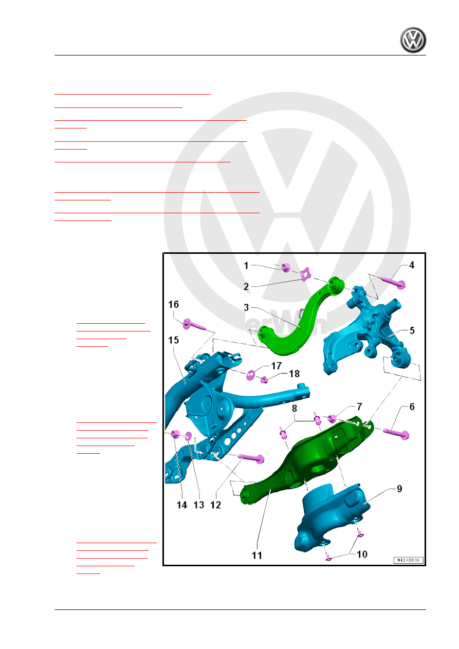
Overview - Transverse Link, Multi-Link Suspension, FWD
1 - Nut
❑ Replace after removal
2 - Washer
3 - Upper Transverse Link
❑ Removing and instal‐
ling. Refer to
4 - Bolt
❑ 130 Nm + 180°
❑ Replace after removal
❑ Always tighten the
threaded connections in
curb weight position.
Refer to
5 - Wheel Bearing Housing
6 - Bolt
❑ 70 Nm + 180°
❑ Replace after removal
❑ Always tighten the
threaded connections in
curb weight position.
Refer to
7 - Nut
❑ Replace after removal