Volkswagen Golf / Golf GTI / Golf Variant. Manual - part 847


  Index      Volkswagen     Volkswagen Golf / Golf GTI / Golf Variant - service repair manual 2013 year


Search            copyright infringement  


Content   ..  845  846  847  848   ..


Volkswagen Golf / Golf GTI / Golf Variant. Manual - part 847


– Unclip the brake line -1- from the clip -arrow- on the left side.

Note

This will destroy the clip, so it will have to be replaced.

– Use the special tools as shown.
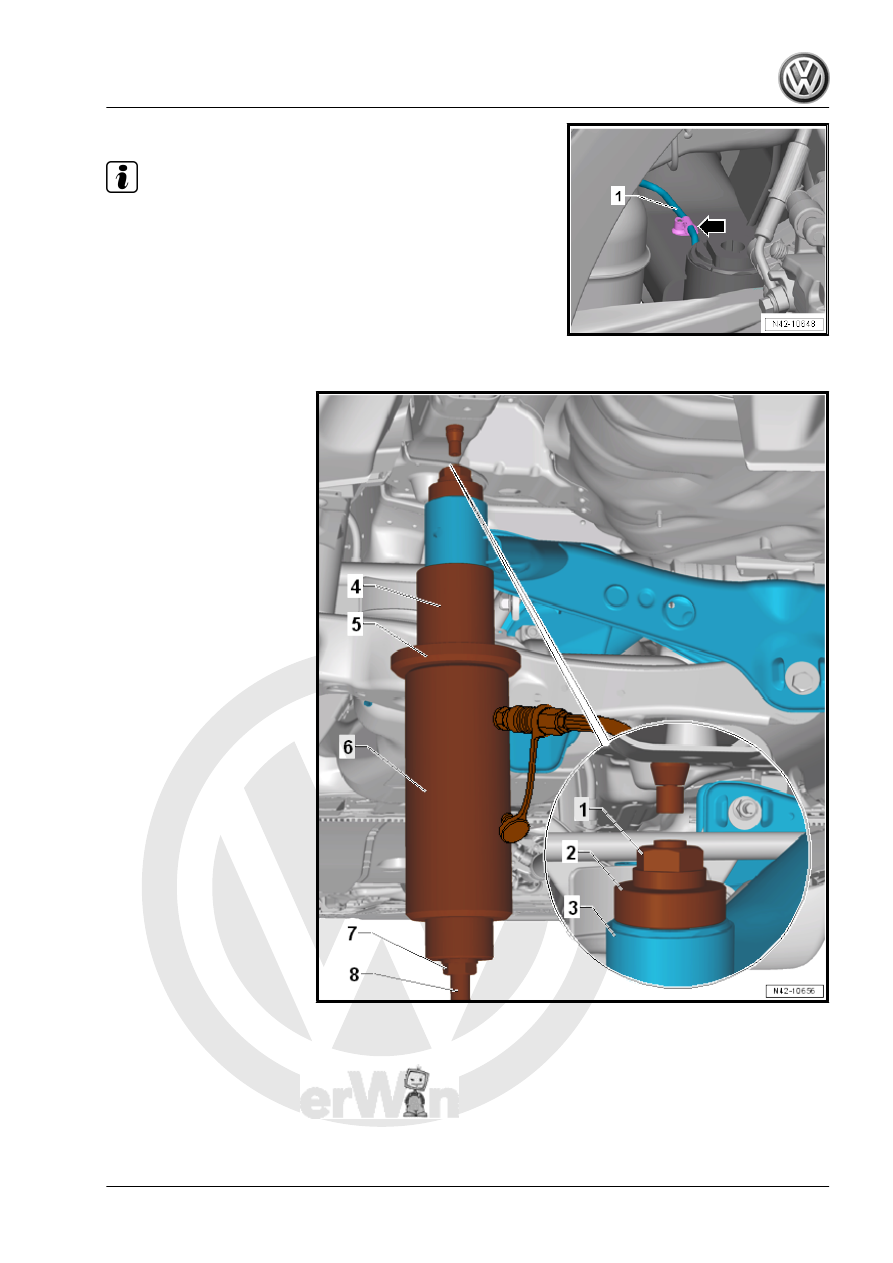
1 - Nut - T10263/5-
2 - Thrust Piece - T10356/5-
3 - Subframe
4 - Tube - T10356/6- , side with offset points to subframe
5 - Gripping Device - T10205/1-

6 - Hydraulic Press - VAS6178- with Pressure Head - T10205/13-
7 - Nut - T10263/5-
8 - Threaded Rod - T10263/4-
– Pretension special tools.
– Press out the bonded rubber mount.

Note

When removing the bonded rubber mounting, the bearing outer race is shorn off. There is a loud crack when

this happens.

After removing the bonded rubber bushing, it must be removed from the Tube - T10356/6- by tapping lightly

with a hammer.

Press In the Rear Bonded Rubber Bushing
– Apply a line -1- on the vertical rib of the bonded rubber bushing

to help mount.

– Apply mounting paste to the outer edge of the bonded rubber

bushing.

– Insert special tools with bonded rubber bushing into subframe

as illustrated.

1 - Nut - T10263/5-
2 - Assembly Tool - Bushing - T10356/7- - the marking -B- points

to the subframe
3 - Subframe
4 - Adjust the bonded rubber bushing to the marks (the marks

need to align)
5 - Assembly Tool - Bushing - T10356/8- - the flattened sides need

to fit into the cover of the bonded rubber bushing -arrows-.
6 - Gripping Device - T10205/1-
7 - Hydraulic Press - VAS6178- with Pressure Head - T10205/13-
8 - Nut - T10263/5-
9 - Threaded Rod - T10263/4-
– Check the position of the bonded rubber bushing and, if nec‐

essary, align and pre-tighten special tools with bonded rubber

bushing.

Note

When installing, make sure the bonded rubber bushing does not

tilt, otherwise the outer ring could be damaged.

– Operate the pump to press in the bonded rubber bushing until

the shoulder is positioned on the subframe “without gap”.

Install in reverse order of removal, note the following:
Tightening Specifications
♦ Refer to

⇒ “3.1.2 Overview - Subframe, Multi-Link Suspension, AWD”,

page 158

♦ Refer to

⇒ “1.1 Wheel Bolt Tightening Specifications”, page 286

♦ Refer to ⇒  Rep. Gr.  26 ; Exhaust Pipes/Mufflers; Overview -

Muffler .


Content   ..  845  846  847  848   ..