Volkswagen Golf / Golf GTI / Golf Variant. Manual - part 763


  Index      Volkswagen     Volkswagen Golf / Golf GTI / Golf Variant - service repair manual 2013 year


Search            copyright infringement  


Content   ..  761  762  763  764   ..


Volkswagen Golf / Golf GTI / Golf Variant. Manual - part 763


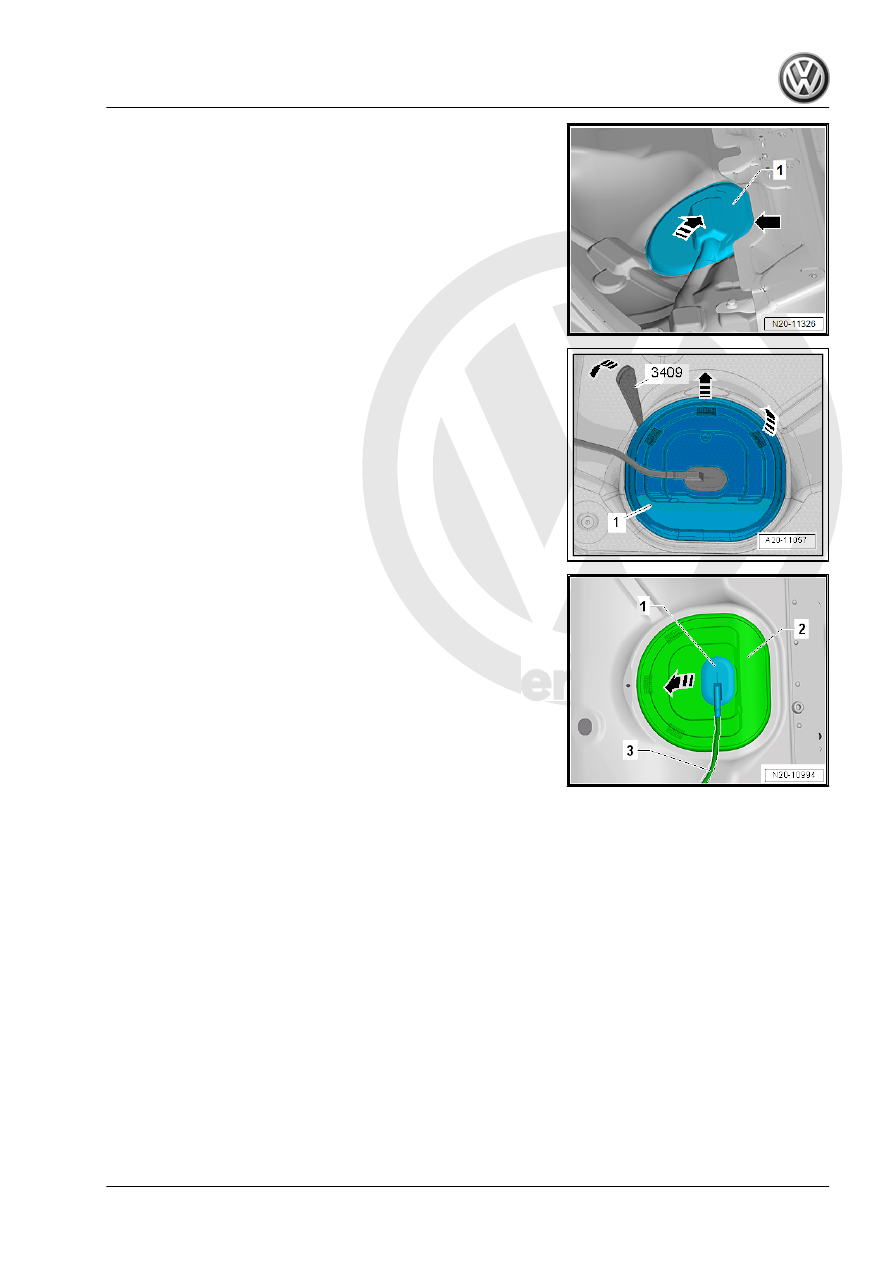
– Partially loosen the cover -1- in the carpet at the separating

line -arrow-.

– Do not separate the cover completely from the carpet so that

later it will be installed correctly.

– Only loosen so far that the cover can be folded up.
– Fold up the cover in the direction of the -arrow-.
Golf and Golf Wagon:
– Remove the rear bench seat. Refer to ⇒  Body Interior; Rep.

Gr.  72 ; Rear Seats; Bench Seat / Single Seats, Removing

and Installing .

Continuation for All Vehicles:
– Unclip the sealing flange cover -1- at the tabs -arrows- using

the -3409- .

– Unclip the grommet -1- downward out of the cover -2-.
– Guide the cover -2- on the wiring harness -3- toward the rear.

– Lift the tab -2- -arrow A- so that it is possible to reach between

the floor panel and the fuel tank.

– At the same time, pull the Fuel Pump Control Module -1- care‐

fully at the wiring harness -3- out of the mount -arrow B-.

– Remove the Fuel Pump Control Module - J538- toward the

inside between the fuel tank and the floor panel.

– Disconnect the connector and remove the Fuel Pump Control

Module - J538- .

Installing
Install in reverse order of removal. Note the following.
Component location. Refer to

⇒ “1.1 Overview - Fuel Tank”, page 6

 .

– Connect the wiring harness to the Fuel Pump Control Module

- J538- .

– Pull on the connector to make sure it is secure.
– Insert the Fuel Pump Control Module - J538- into the mount

on the fuel tank and press on it until it clicks into place.

– Pull on the Fuel Pump Control Module - J538- to make sure it

is secure.

9

Sensors

⇒ “9.1  Fuel Tank Pressure Sensor G400 , Removing and Instal‐

ling”, page 119
⇒ “9.2  Fuel Tank Leak Detection Control Module J909 , Remov‐

ing and Installing”, page 120

9.1

Fuel Tank Pressure Sensor - G400- ,

Removing and Installing

Removing

Note

The Fuel Tank Pressure Sensor - G400- is located in the pressure

regulating valve on the EVAP canister. Refer to

⇒ “6.2.2 Overview - EVAP System, without Fuel Tank Leak De‐

tection”, page 70

 .

– Remove the EVAP canister. Refer to

⇒ “6.3.2 EVAP Canister, Removing and Installing, without Fuel

Tank Leak Detection”, page 71

 .

– Remove the hose -1- to the EVAP canister -2-.
– To do this, loosen the clamps -arrows-.

– Remove the bolts -arrows- for the pressure regulating valve

-1- on the EVAP canister -2-.

– Remove the pressure regulating valve -1- from the seal -3- on

the EVAP canister -2- in the -direction of the arrow-.

Installing

Install in reverse order of removal. Note the following:
– Pay attention that the seal -3- is seated correctly.
Tightening Specification
♦ Refer to

⇒ “6.2.2 Overview - EVAP System, without Fuel Tank Leak

Detection”, page 70

9.2

Fuel Tank Leak Detection Control Mod‐

ule - J909- , Removing and Installing

Removing
Component location 

⇒ Item 17 (page 11)

 :

– Release and remove the connector -arrow- on the Fuel Tank

Leak Detection Control Module - J909- -1-.

– Push the Fuel Tank Leak Detection Control Module - J909-

-1- upward evenly on both sides -arrows-, until it engages

audibly.

– Remove the Fuel Tank Leak Detection Control Module - J909-

-1- from the bracket -2-.

Installing
Install in reverse order of removal. Note the following.


Content   ..  761  762  763  764   ..