Volkswagen Golf / Golf GTI / Golf Variant. Manual - part 762


  Index      Volkswagen     Volkswagen Golf / Golf GTI / Golf Variant - service repair manual 2013 year


Search            copyright infringement  


Content   ..  760  761  762  763   ..


Volkswagen Golf / Golf GTI / Golf Variant. Manual - part 762


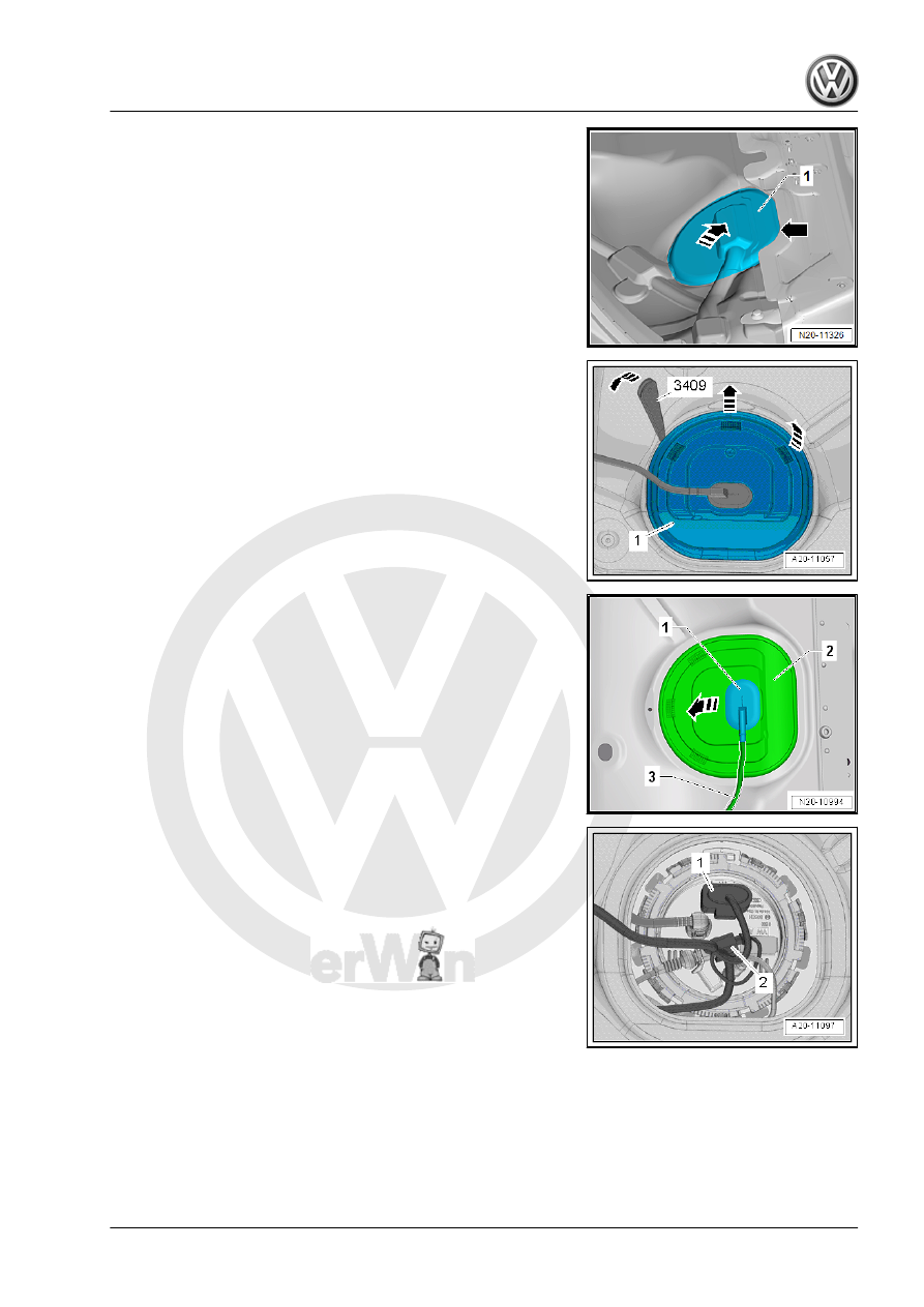
– Partially loosen the cover -1- in the carpet at the separating

line -arrow-.

– Do not separate the cover completely from the carpet so that

later it will be installed correctly.

– Only loosen so far that the cover can be folded up.
– Fold up the cover in the direction of the -arrow-.
Golf and Golf Wagon:
– Remove the rear bench seat. Refer to ⇒  Body Interior; Rep.

Gr.  72 ; Rear Seats; Bench Seat / Single Seats, Removing

and Installing .

Continuation for All Vehicles:
– Unclip the sealing flange cover -1- at the tabs -arrows- using

the -3409- .

– Unclip the grommet -1- downward out of the cover -2-.
– Guide the cover -2- on the wiring harness -3- toward the rear.

– Pull on the connector -1- without pressing the release to make

sure the connection is secure. If the connector was not con‐

nected correctly, it could cause a malfunction.

– Release and disconnect the connector -1-.
– Check the contacts on the connector and on the fuel delivery

unit for damage.

– Attach the -VAS5565- to the connector and to the fuel delivery

unit.

– Connect the -VAG1348/3A- to the -VAS5565- and the battery

positive terminal clamp in the engine compartment.

Note

This step allows the fuel pump to run when the engine is not run‐

ning.

– The fuel pump delivery rate is dependent on the battery volt‐

age. Also connect the Multimeter to the wires -1- and -5- in the

-VAS5565- .

– To do so, use the -VAG1594D- also.

– Remove the fuel lines -1- from the flange. Disconnect the con‐

nector couplings. Refer to

⇒ “4.1 Connector Couplings, Disconnecting”, page 62

 .

WARNING

The fuel line is under pressure.
Fuel poses a risk of injury to the eyes and skin.
Wear protective eyewear and protective clothing to avoid injury

and contact with skin. Place a cleaning cloth around the con‐

nection  point  before  loosening  hose  connections.  Carefully

open the connection point to release the pressure.

– Connect the -VAS6550- to the fuel delivery unit -1- using the

-VAS6550/3-4- .

– Connect the -VAS6550/3-4- to the shut-off valve -A-.
– Connect the -VAS6550/4- to the connection -B- on the -

VAS6550- .

– Hold the open end of the -VAS6550/4- hose in a measuring

container.

– Make sure that the drain valve -C- on the Pressure Tester

-1- is closed.

– The shut-off valves -A and B- on the Pressure Tester Kit -1-

are opened.

– Push the -VAG1348/3A- .

Note

The Transfer Fuel Pump - G6- is activated!

– Adjust the pressure to 4.0 bar with the adjustment wheel on

the Pressure Regulating Valve -arrow-.

– From this point on do not move the adjustment wheel.
– Empty the measuring container.
– Press the remote control for 60 seconds while measuring the

fuel pump voltage.

– Compare the delivered quantity of fuel with the specified value

in the table.

Axis designation

Unit

Minimum delivery rate

cm

3

Fuel pump voltage when the

engine is idling and the pump is

running

Volt

Example:
During test, a voltage of 10.5 Volts is measured. This results in a

minimum delivery quantity of approximately 1200 cm

3

/60 s.

If the Specified Value is Obtained:
– Check the fuel lines for possible restrictions (kinks) or block‐

ages.

– Check the fuel lines for leaks and damage.
If the Specified Value is not Obtained:
– Remove the fuel delivery unit. Refer to

⇒ “2.2 Fuel Delivery Unit/Fuel Level Sensor, Removing and

Installing”, page 52

 .

– Check the filter screen for contaminants.
– Check whether the hose connections -arrows- to the fuel de‐

livery unit -1- are sealed.

– Check the fuel lines for possible restrictions (kinks) or block‐

ages.

– Check the fuel lines for leaks and damage.
If no Malfunction was Detected:
– Replace the fuel delivery unit. Refer to

⇒ “2.2 Fuel Delivery Unit/Fuel Level Sensor, Removing and

Installing”, page 52

 .

8.2

Fuel Pump Control Module - J538- , Re‐

moving and Installing

Special tools and workshop equipment required
♦ Trim Removal Wedge - 3409-
Procedure:
Removing
– Move the front seats all the way forward.
– Switch off the ignition.
Golf Sportsvan:
– Remove the right rear seat. Refer to ⇒  Body Interior; Rep. Gr. 

72 ; Rear Seats; Bench Seat / Single Seat, Removing and In‐

stalling .


Content   ..  760  761  762  763   ..