Volkswagen Golf / Golf GTI / Golf Variant. Manual - part 740


  Index      Volkswagen     Volkswagen Golf / Golf GTI / Golf Variant - service repair manual 2013 year


Search            copyright infringement  


Content   ..  738  739  740  741   ..


Volkswagen Golf / Golf GTI / Golf Variant. Manual - part 740


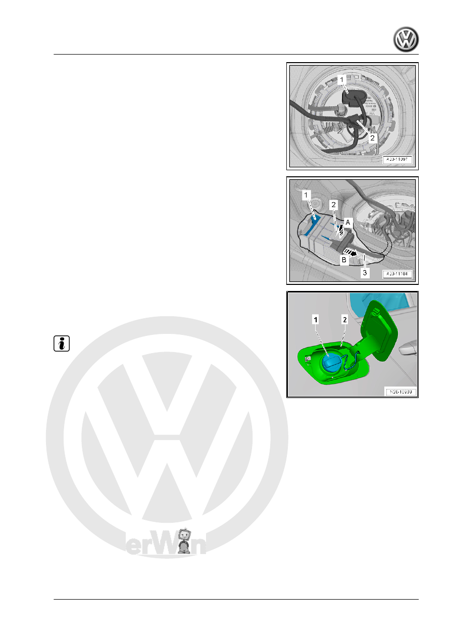
– Unlock and disconnect the connectors -1- from the sealing

flange.

– If equipped, release the connector -2- for the Metering Pump

- V54- and remove it.

– Disconnect the connector -2-.

– Lift the tab -2- in the direction of the -arrow A-.
– To do so, reach a finger between the floor panel and the fuel

tank.

– At the same time, carefully pull the Fuel Pump Control Module

- J538- -1- out of the mount at the wiring harness -3- in the

direction of the -arrow B-.

– Remove the Fuel Pump Control Module - J538- toward the

inside between the fuel tank and the floor panel.

– Open the fuel filler door unit -2-.
– Clean the area around the fuel filler neck.
– Remove the cap -1- for the fuel filler neck.

Note

Seal the fuel filler neck opening with a clean plug to prevent any

dirt from getting in.

– Remove the fuel filler door unit -2-. Refer to ⇒  Body Exterior;

Rep. Gr.  55 ; Fuel Filler Door Unit; Fuel Filler Door Unit, Re‐

moving and Installing .

– Remove the right rear wheel. Refer to ⇒  Suspension, Wheels,

Steering; Rep. Gr.  44 ; Wheels, Tires; Changing a Wheel .

– Remove the right rear wheel housing liner. Refer to ⇒  Body

Exterior; Rep. Gr.  66 ; Wheel Housing Liner; Overview - Rear

Wheel Housing Liner .

– Remove the rear underbody trim panel. Refer to ⇒  Body Ex‐

terior; Rep. Gr.  66 ; Underbody Trim Panel; Underbody Trim

Panels, Removing and Installing .

– Disconnect the vent lines -1 and 2- from the EVAP canister.

Disconnect the connector couplings. Refer to

⇒ “4.1 Connector Couplings, Disconnecting”, page 62

 .

– Unclip the breather line from bracket -arrows-.

– Unclip the breather lines -1- at the bracket -arrow-.
– Remove the rear axle. Refer to ⇒  Suspension, Wheels, Steer‐

ing; Rep. Gr.  42 ; Rear Axle; Rear Axle, Removing and

Installing .

– Remove the exhaust system rear section. Refer to ⇒  Rep. Gr. 

26 ; Exhaust Pipes/Mufflers; Overview - Muffler .

– Remove the fuel filler neck bolts -1 and 2-.

– Remove the fuel line -1- from the underbody. Disconnect the

connector couplings. Refer to

⇒ “4.1 Connector Couplings, Disconnecting”, page 62

 .

WARNING

The fuel line is under pressure.
Fuel poses a risk of injury to the eyes and skin.
Wear protective eyewear and protective clothing to avoid injury

and contact with skin. Place a cleaning cloth around the con‐

nection  point  before  loosening  hose  connections.  Carefully

open the connection point to release the pressure.

– Disconnect the breather line -2-. Disconnect the connector

couplings. Refer to

⇒ “4.1 Connector Couplings, Disconnecting”, page 62

 .

Vehicles with Parking Heater:
– Remove the fuel line -1- from the parking heater. Disconnect

the connector couplings. Refer to

⇒ “4.1 Connector Couplings, Disconnecting”, page 62

 .

– If equipped, remove the rear underbody trim panel. Refer to

⇒  Body Exterior; Rep. Gr.  66 ; Underbody Trim Panel; Un‐

derbody Trim Panels, Removing and Installing .

Continuation for All Vehicles:
– Remove the bolt -5-.
– Remove the bracket for the exhaust system -arrow-.
– Remove the bolt -3- and remove the mounting strap -7-.

– Place the -VAS6931- under the fuel tank -1- to support it as

illustrated.

– Remove the bolts -2, 4 and 6-.

Note

To improve clarity, the fuel tank is shown without the -

VAS6931- .

A second technician is required to remove the fuel tank.

– Lower the fuel tank -1- using the -VAS6931- .
Installing
Install in reverse order of removal. Note the following:

Note

Disconnect the connector couplings. Refer to

⇒ “4.1 Connector Couplings, Disconnecting”, page 62

 .

– If equipped, make sure the Metering Pump - V54- is seated

securely.

– Make sure the vent and fuel lines are routed without kinks.
– Make sure to guide the fuel filler neck correctly into the opening

in the body.

– Position the fuel tank together with the mounting strap on the

underbody using the -VAS6931- .

– Note the location of the mounting strap.
– Make sure the supply, return and breather lines are still clipped

to the fuel tank after the fuel tank has been installed.

– Note the correct installation location for the exhaust system

bracket. Refer to ⇒  Rep. Gr.  26 ; Exhaust Pipes/Muffler;

Overview - Muffler .

– Make sure the line connections are secure.
– Check the fit by pulling on it.


Content   ..  738  739  740  741   ..