Volkswagen Golf / Golf GTI / Golf Variant. Manual - part 739


  Index      Volkswagen     Volkswagen Golf / Golf GTI / Golf Variant - service repair manual 2013 year


Search            copyright infringement  


Content   ..  737  738  739  740   ..


Volkswagen Golf / Golf GTI / Golf Variant. Manual - part 739


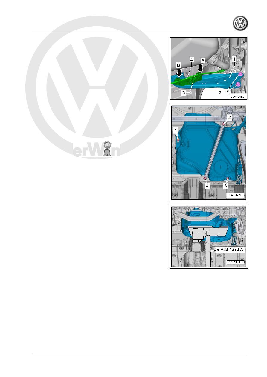
– Unclip the parking brake cable -4- from the bracket

-arrow A-.

– Pull the parking brake cable out of the guide -arrow B- on the

bracket -3-.

– Remove the bolts -2- and pivot the trailing arm -1- downward.

– Remove the bolt -4-.
– Remove the bracket for the exhaust system.
– Remove the bolt -2- and remove the mounting strap.

– Place the -VAS6931- under the fuel tank for support.

– Remove the bolts -1 and 3-.

Note

To improve clarity, the fuel tank is shown without the -

VAS6931- .

A second technician is required to remove the fuel tank.

– Lower the fuel tank using the -VAS6931- .
– By turning it accordingly, lower the fuel tank sideways.
– Pay attention to the lines to the EVAP canister, unclipping

them if necessary.

– Guide the filler neck out between the rear axle and the body.
Installing
Install in reverse order of removal. Note the following:
– Guide the filler neck between the rear axle and the body.

Note

Disconnect the connector couplings. Refer to

⇒ “4.1 Connector Couplings, Disconnecting”, page 62

 .

– If equipped, make sure the Metering Pump - V54- is seated

securely on the bracket.

– Make sure to guide the fuel filler neck correctly into the opening

in the body.

– Make sure the vent and fuel lines are routed without kinks.
– Make sure the supply, return and breather lines are still clipped

to the fuel tank after the fuel tank has been installed.

– Position the fuel tank together with the mounting strap on the

underbody using the -VAS6931- .

– Note the correct installation location for the exhaust system

bracket. Refer to ⇒  Rep. Gr.  26 ; Exhaust Pipes/Muffler;

Overview - Muffler .

– Note the location of the mounting strap.
– Make sure the line connections are secure.
– Check the fit by pulling on it.

Pro

te

c

t

ed

  b

y

  co

p

y

rig

h

t

C

o

p

y

in

g

  fo

pr

iv

a

t

e

 o

r

 c

o

m

m

e

r

c

ia

p

u

rp

o

s

e

s

,

 i

n

 p

a

rt

o

r i

n

 w

h

o

le

is

 n

o

t

 p

e

r

m

it

t

e

d

 u

n

l

e

s

s

 a

ut

ho

r

i

s

ed

 b

y

 V

olk

sw

a

ge

n AG

.


V

olk

s

w

a

g

en

 AG do

es 

n

ot g

uar

ante

e

 or a

c

c

ep

t

 a

ny


li

a

b

i

li

t

y

 w

ith

 r

e

s

p

e

c

t

 t

o


th

e

 c

o

rr

e

c

t

n

e

s

s


o

f

in

fo

r

m

a

tio

n

 in

 th

is

 d

o

c

um

en

t.

C

o

py

rig

ht b

y


V

olk

sw

a

ge

n


A

G.

– Check the ground cable for traces of oxidation on the connec‐

tors. Remove any oxidation if necessary.

– Check the installation position of the ground connection.
• The connector -2- must be securely attached to the metal ring

-3-.

• The contact -1- must be engaged in the fuel tank -4- and se‐

cured with the spacer -5-.

– Check the metal ring connection on the fuel filler neck to a bare

area on the body with an ohmmeter.

• Specified value is approximately 0 ohm.
• If the specified values is incorrect, then there is a risk of ex‐

plosion due to electrostatic discharge.

– Fill at least five liters of fuel in the fuel tank.

WARNING

There is a risk of the fuel tank exploding! After installing a new

or completely emptied fuel tank, fill it immediately with a mini‐

mum of five liters of fuel. Do not allow the fuel pump to run when

the fuel tank is completely empty.

Tightening Specifications
♦ Refer to

⇒ “1.1.1 Overview - Fuel Tank, Vehicles with Multi-Link Rear

Axle and FWD”, page 6

♦ Refer to ⇒  Body Interior; Rep. Gr.  72 ; Rear Seats; Bench

Seat / Single Seats, Removing and Installing .

♦ Refer to ⇒  Rep. Gr.  26 ; Exhaust Pipes/Mufflers; Overview -

Muffler .

♦ Refer to ⇒  Body Exterior; Rep. Gr.  55 ; Fuel Filler Door Unit;

Fuel Filler Door Unit, Removing and Installing .

♦ Refer to ⇒  Body Exterior; Rep. Gr.  66 ; Underbody Trim Pan‐

el .

♦ Refer to ⇒  Suspension, Wheels, Steering; Rep. Gr.  42 ;

Wheel Bearing, Trailing Arm; Overview - Trailing Arm .

1.2.3

Fuel Tank, Removing and Installing, Ve‐

hicles with Torsion Beam Rear Suspen‐

sion

Special tools and workshop equipment required
♦ Trim Removal Wedge - 3409-
♦ Torque Wrench 1331 5-50Nm - VAG1331-
♦ Torque Wrench 1332 40-200Nm - VAG1332-
♦ Engine and Gearbox Jack - VAS6931-
Removing
– Observe the safety instructions. Refer to

⇒ “1 Safety Precautions”, page 1

 .

– Follow the guidelines for clean working conditions. Refer to

⇒ “3.1 Parking/Auxiliary Heater and Fuel System Clean Work‐

ing Conditions”, page 4

 .

– Drain the fuel tank. Refer to

⇒ “1.3 Fuel Tank, Draining”, page 35

 .

– Move the front seats all the way forward.
– Switch off the ignition.
Golf Sportsvan:
– Remove the right rear seat. Refer to ⇒  Body Interior; Rep. Gr. 

72 ; Rear Seats; Bench Seat / Single Seat, Removing and In‐

stalling .

– Partially loosen the cover -1- in the carpet at the separating

line -arrow-.

– Do not separate the cover completely from the carpet so that

later it will be installed correctly.

– Only loosen so far that the cover can be folded up.
– Fold up the cover in the direction of the -arrow-.
Golf and Golf Wagon:
– Remove the rear bench seat. Refer to ⇒  Body Interior; Rep.

Gr.  72 ; Rear Seats; Bench Seat / Single Seats, Removing

and Installing .

Continuation for All Vehicles:
– Unclip the sealing flange cover -1- at the tabs -arrows- using

the -3409- .

– Unclip the grommet -1- downward out of the cover -2-.
– Guide the cover -2- on the wiring harness -3- toward the rear.


Content   ..  737  738  739  740   ..