Volkswagen Golf / Golf GTI / Golf Variant. Manual - part 725


  Index      Volkswagen     Volkswagen Golf / Golf GTI / Golf Variant - service repair manual 2013 year


Search            copyright infringement  


Content   ..  723  724  725  726   ..


Volkswagen Golf / Golf GTI / Golf Variant. Manual - part 725


9

Special Tools

Special tools and workshop equipment required
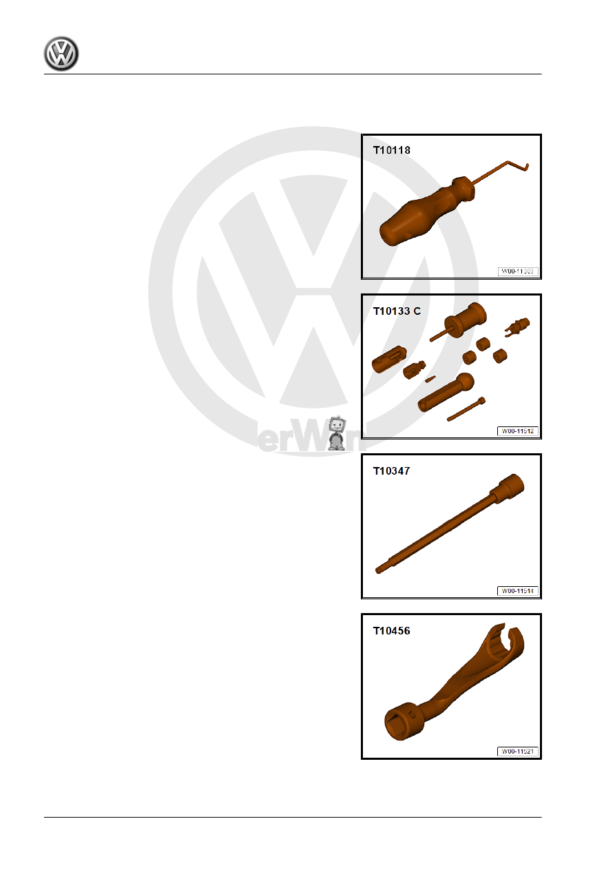
♦ Elbow Assembly Tool - T10118-

♦ Injector/Combustion Chamber Seal Tool Set - T10133C-

♦ Torx Socket - T30 - T10347-

♦ Flare Nut Attachment - 17mm - T10456-

♦ Socket - 27mm - T40218-

♦ Wiring Harness Repair Set - Hot Air Blower - VAS1978/14A-

-1- with nozzle attachment -2- from the Wiring Harness Repair

Set - VAS1978B- .

♦ Ring Wrench 7-Piece Set - 3337-

♦ Not Illustrated:
♦ Ultrasonic Cleaning Unit - VAS6418-
♦ Mounting Plate for Injection Modules - VAS6418/1-
♦ Cleaning Fluid - VAS6418/2-
♦ Pressure Sensor Tester - VAS6394-
♦ Adapter - VAS6394/2-
♦ Vehicle Diagnostic Tester - Test Adapter - 3 Pin - VAS5570-
♦ Torque Wrench 1331 5-50Nm - VAG1331-
♦ Vehicle Diagnostic Tester

26 – Exhaust System, Emission Controls

1

Exhaust Pipes/Mufflers

⇒ “1.1 Overview - Muffler”, page 338
⇒ “1.2 Exhaust Pipes/Mufflers, Separating”, page 342
⇒ “1.3 Muffler, Removing and Installing”, page 343
⇒ “1.4 Exhaust System, Installing without Tension”, page 345
⇒ “1.5 Exhaust System, Checking for Leaks”, page 346
⇒ “1.6 Clamping Sleeve Installation Position”, page 347

1.1

Overview - Muffler

⇒ “1.1.1 Overview - Muffler, Golf with 2.0L Engine ”, page 338
⇒ “1.1.2 Overview - Muffler, Golf with 1.8L Engine ”, page 340
⇒ “1.1.3 Overview - Muffler, Golf Wagon”, page 341

1.1.1

Overview - Muffler, Golf with 2.0L Engine

1 - Front Clamping Sleeve

❑ Before tightening, align

exhaust system free of

tension. Refer to

⇒ “1.4 Exhaust System,

Installing without Ten‐

sion”, page 345

 .

❑ Tighten threaded con‐

nections evenly.

❑ Tightening specifica‐

tion. Refer to

⇒ Fig. ““Tightening

Specification of Clamp‐

ing Sleeve”“ ,

page 347

 .

2 - Center Muffler

❑ Original equipment as

one unit with rear muf‐

fler. For repairs, replace

each separately

❑ Removing and instal‐

ling. Refer to

⇒ “1.3 Muffler, Remov‐

ing and Installing”, page

343

 .

❑ Separating point. Refer

to

⇒ “1.2 Exhaust Pipes/

Mufflers, Separating”,

page 342

 .

❑ Exhaust System, Instal‐

ling without Tension.

Refer to

⇒ “1.4 Exhaust System,

Installing without Ten‐

sion”, page 345

 .

3 - Bolt

❑ 20 Nm

4 - Bracket
5 - Retaining Loop

❑ Replace if damaged

6 - Rear Muffler

❑ Original equipment as one unit with rear muffler. For repairs, replace each separately
❑ Removing and installing. Refer to 

⇒ “1.3 Muffler, Removing and Installing”, page 343

 .

❑ Separating point. Refer to 

⇒ “1.2 Exhaust Pipes/Mufflers, Separating”, page 342

 .

❑ Exhaust System, Installing without Tension. Refer to

⇒ “1.4 Exhaust System, Installing without Tension”, page 345

 .

7 - Rear Clamping Sleeve

❑ Before tightening, align exhaust system free of tension. Refer to

⇒ “1.4 Exhaust System, Installing without Tension”, page 345

 .

❑ Installed position. Refer to 

⇒ Fig. ““Installation Position for Rear Clamping Sleeve”“ , page 347

❑ Tighten threaded connections evenly.
❑ Tightening specification. Refer to 

⇒ Fig. ““Tightening Specification of Clamping Sleeve”“ , page 347

 .


Content   ..  723  724  725  726   ..