Volkswagen Golf / Golf GTI / Golf Variant. Manual - part 723


  Index      Volkswagen     Volkswagen Golf / Golf GTI / Golf Variant - service repair manual 2013 year


Search            copyright infringement  


Content   ..  721  722  723  724   ..


Volkswagen Golf / Golf GTI / Golf Variant. Manual - part 723


❑ If the connection was loosened, it must be replaced.

12 - Fuel Supply Line
13 - Spring Clamp

❑ Replace after removing

7.2

High Pressure Pump, Removing and In‐

stalling

Special tools and workshop equipment required
♦ Flare Nut Attachment - 17mm - T10456-

Caution

This procedure contains mandatory replaceable parts. Refer

to component overview prior to starting procedure.

Mandatory Replacement Parts
♦ Bolts - High Pressure Pump

Note

Only remove the high pressure pump when the engine is cold.

Pay attention when installing the high pressure pump, that no

dirt enters the fuel system.

Collect escaping fuel with a rag.

Inspect the O-ring for the high pressure pump, and replace it

if damaged.

If the connection for the high pressure line -item 11-

⇒ Item 11 (page 327)

 was loosened, it must be replaced.

Lubricate the high pressure line with engine oil and always

fasten them free of tension.

Vehicles with the engine codes CNTA do not have an intake

manifold-fuel injector.

CAUTION

Fuel system is under high pressure.
Risk of injury from fuel spraying out.
– Reducing the fuel high pressure.
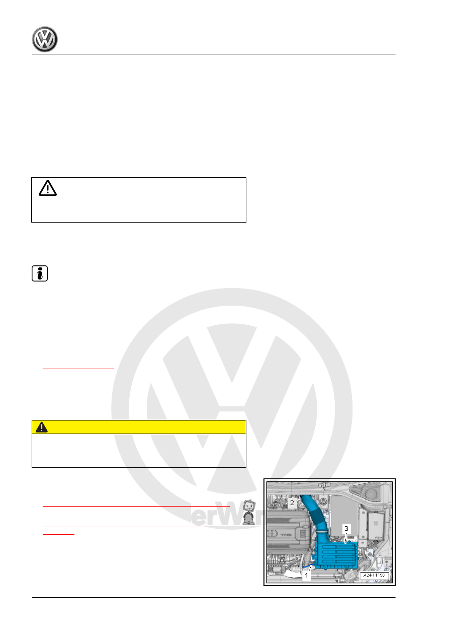
Removing
– Remove the engine cover. Refer to

⇒ “3.1 Engine Cover, Removing and Installing”, page 38

 .

– Remove the air filter housing -3-. Refer to

⇒ “3.2 Air Filter Housing, Removing and Installing”,

page 294

 .

– Free up the wiring harness -1 and 2- from the air guide pipe.
– Loosen the screw-type clamp -3-.
– Remove the bolts -arrows-.

– Loosen the hose clamp -arrow- and remove the left charge air

hose -1- with the air guide pipe downward.

– Release the retainers -arrow-, remove the wiring duct upward

from the bracket and move it towards the front.

– Remove the bolts -1, 2 and 3-.

– Remove the pipe clamp -arrow-.

– Loosen the union nut on the fuel rail -arrow- with the Flare Nut

Attachment - 17mm - T10456- .

– Counterhold on the hex fitting -A- and loosen the union nut

-arrow-. Remove the high pressure line.

– Disconnect the connector -1- from the Fuel Pressure Regula‐

tor Valve - N276- .

Vehicles with Intake-Manifold Fuel Injection

– Remove the fuel hose -3-.

For All Vehicles
– Remove the fuel hose -2-.
– Remove the bolts -arrows-.
– Carefully remove the high pressure pump. The roller tappet

can possibly remain in the vacuum pump.

Installing
– Replace the high pressure pump O-ring if damaged.
– Inspect the roller tappet for damages before installing and re‐

place if necessary.

– Insert the roller tappet into the vacuum pump as shown.

Note

To insert the high pressure pump, the roller tappet must be at

its lowest point.

If the connection for the high pressure line -item 11-

⇒ Item 11 (page 327)

 was loosened, it must be replaced.

– Rotate the crankshaft until the roller tappet is at the lowest

point.

– Insert the high pressure pump in the vacuum pump.

– Tighten the bolts -arrows- by hand in a diagonal sequence.
– Tighten the bolts diagonally to the tightening specification. For

the tightening specifications. Refer to

⇒ “7.1 Overview - High Pressure Pump”, page 325

 .

– Attach the fuel hoses -2 and 3- if equipped and secure with the

spring clamp.

– Connect the connector -1- to the Fuel Pressure Regulator

Valve - N276- .

– Coat the high pressure line ball with engine oil and install the

high pressure line. Tighten the union nut hand-tight and align

the high pressure line free of tension.

– Tighten the union nut on the fuel rail -arrow- with the Flare Nut

Attachment - 17mm - T10456- .

– Counterhold on the hex fitting -A- and tighten the union nut

-arrow-.


Content   ..  721  722  723  724   ..