Volkswagen Golf / Golf GTI / Golf Variant. Manual - part 707


  Index      Volkswagen     Volkswagen Golf / Golf GTI / Golf Variant - service repair manual 2013 year


Search            copyright infringement  


Content   ..  705  706  707  708   ..


Volkswagen Golf / Golf GTI / Golf Variant. Manual - part 707


2

Charge Air System

⇒ “2.1 Overview - Charge Air System”, page 264

 .

⇒ “2.2 Overview - Charge Air Hose Connections”, page 265

 .

⇒ “2.3 Charge Air Cooler, Removing and Installing”, page 265

 .

⇒ “2.4  Charge Air Pressure Sensor G31 , Removing and Instal‐

ling”, page 269

 .

⇒ “2.5 Charge Air System, Checking for Leaks”, page 269

 .

2.1

Overview - Charge Air System

Note

Assembly of screw-type clamps for the charge air hose connections. Refer to

⇒ “2.2 Overview - Charge Air Hose Connections”, page 265

 .

Before testing or performing a repair, check all air guide pipes and hoses and all vacuum lines for leaks and

secure seating.

Follow the guidelines for clean working conditions. Refer to 

⇒ “3.1 Clean Working Conditions”, page 5
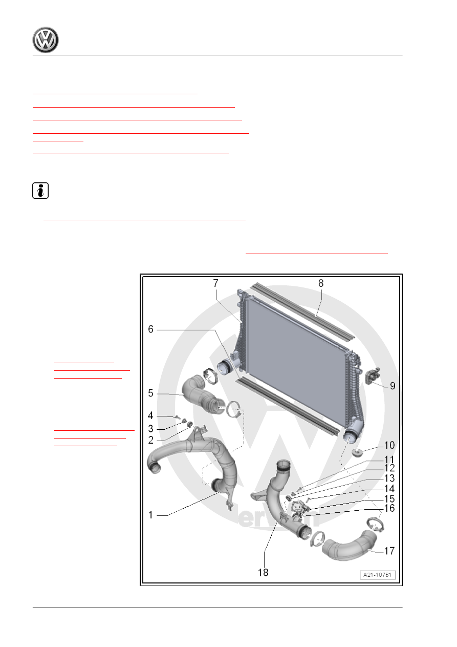
 .

1 - Air Guide Pipe
2 - Grommet
3 - Spacer Sleeve
4 - Bolt

❑ 7 Nm

5 - Air Guide Hose

❑ Installing. Refer to

⇒ “2.2 Overview -

Charge Air Hose Con‐

nections”, page 265

 .

6 - Air Guide
7 - Charge Air Cooler

❑ Removing and instal‐

ling. Refer to

⇒ “2.3 Charge Air Cool‐

er, Removing and In‐

stalling”, page 265

 .

8 - Air Guide
9 - Rubber Bushing

❑ For the charge air cooler

10 - Rubber Bushing

❑ For the charge air cooler

11 - Bolt

❑ 7 Nm

12 - Spacer Sleeve
13 - Grommet
14 - Bolt

❑ 5 Nm

15 - Charge Air Pressure Sensor - G31-

❑ Removing and installing. Refer to

⇒ “2.4  Charge Air Pressure Sensor G31 , Removing and Installing”, page 269

 .

16 - O-Ring

❑ Replace after removing

17 - Air Guide Hose

❑ Installing. Refer to 

⇒ “2.2 Overview - Charge Air Hose Connections”, page 265

 .

18 - Air Guide Pipe

2.2

Overview - Charge Air Hose Connec‐

tions

Installing Hose Connections with Threaded Connections

Note

Tighten the clamps -A- on the charge air pipes to 5.5 Nm. An

insufficient or excessive tightening torque can cause the charge

air hose to come off the charge air pipe while driving.

– Before testing or performing a repair, check all air guide pipes

and hoses and all vacuum lines for leaks and secure seating.

– Clean the hose connections as well as the air guide pipes and

hoses before installing, they must be free of oil and grease.

– Secure hose connections with standard production clamps.

Refer to the Parts Catalog.

– The screws on the used clamps must be sprayed with a rust

remover before installing.

2.3

Charge Air Cooler, Removing and In‐

stalling

Special tools and workshop equipment required
♦ Engine Bung Set - VAS6122-

Caution

This procedure contains mandatory replaceable parts. Refer

to component overview prior to starting procedure.

Mandatory Replacement Parts
♦ O-rings - Charge Air Cooler
Removing
– Remove the fan shroud. Refer to

⇒ “4.5 Fan Shroud, Removing and Installing”, page 249

 .

– Remove the radiator. Refer to

⇒ “4.4 Radiator, Removing and Installing”, page 247

 .

– Remove the front bumper cover. Refer to ⇒  Body Exterior;

Rep. Gr.  63 ; Front Bumper; Bumper Cover, Removing and

Installing .

– Remove the bolts -1 and 3-.

– Open the retainer in direction of -arrow- and remove the cover

-2-.

– Free up the coolant hose -2-.
– Open the retaining tabs in direction of -arrows-, remove the

upper air duct -1-.

– Remove the left and right bolts -arrow-.
– Unclip the air guide lower section -1- and remove.

– Lift the clamp -arrow- and remove the upper left coolant hose

from the radiator.

– Remove the center guide -A- from the lock carrier -arrows-.

– Remove the left and right radiator mount catches in direction

of -arrows- with a side cutter. Push the upper coolant radiator

slightly to the engine.

Note

The radiator mount with be used again when installing. It is then

attached to the lock carrier. Bolts. Refer to the Parts Catalog.

– Loosen the clamps -1 and 2- and remove the air guide hose.
– Seal the open lines and connections with clean plugs from the

Engine Bung Set - VAS6122- .

– Have a second technician release the retaining clamps -1- in

the direction of -arrow A- . Remove the condenser -3- upward

out of the mounts in direction of -arrows B- .

– Secure the condenser to the lock carrier.

– Remove the charge air cooler downward.


Content   ..  705  706  707  708   ..