Volkswagen Golf / Golf GTI / Golf Variant. Manual - part 705
 

  Index      Volkswagen     Volkswagen Golf / Golf GTI / Golf Variant - service repair manual 2013 year


Search            copyright infringement  


Content   ..  703  704  705  706   ..


Volkswagen Golf / Golf GTI / Golf Variant. Manual - part 705


21 – Turbocharger, Supercharger

1

Turbocharger

⇒ “1.1 Overview - Turbocharger”, page 256

 .

⇒ “1.2 Turbocharger, Removing and Installing”, page 258

 .

⇒ “1.3  Charge Pressure Actuator V465 , Adjusting”, page 263

 .

1.1

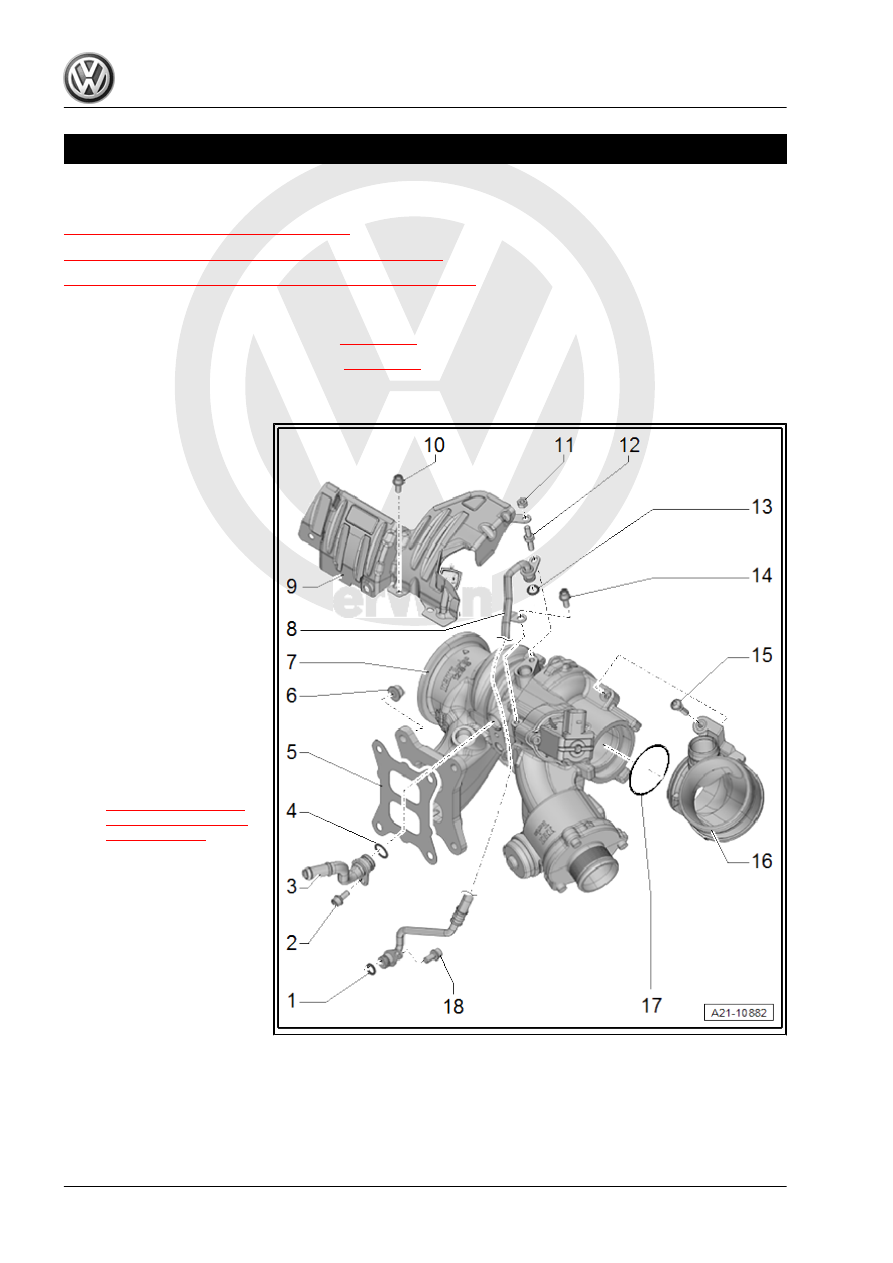
Overview - Turbocharger

Overview - Turbocharger, Part I. Refer to 

⇒ page 256

 .

Overview - Turbocharger, Part II. Refer to 

⇒ page 257

 .

Overview - Turbocharger, Part I

1 - O-Ring

❑ Replace after removing
❑ Coat with engine oil

2 - Bolt

❑ 9 Nm

3 - Coolant Supply Line
4 - O-Ring

❑ Replace after removing
❑ Coat with coolant

5 - Seal

❑ Replace after removing

6 - Nut

❑ 25 Nm
❑ Replace after removing

7 - Turbocharger

❑ Removing and instal‐

ling. Refer to

⇒ “1.2 Turbocharger,

Removing and Instal‐

ling”, page 258

 .

8 - Oil Supply Line
9 - Heat Shield
10 - Bolt

❑ 9 Nm

11 - Nut

❑ 9 Nm

12 - Bolt

❑ 9 Nm

13 - O-Ring

❑ Replace after removing
❑ Coat with engine oil

14 - Bolt

❑ 9 Nm

15 - Bolt

❑ 9 Nm

16 - Connection
17 - O-Ring

❑ Replace after removing

18 - Bolt

❑ 9 Nm

Overview - Turbocharger, Part II

1 - Bolt

❑ 9 Nm

2 - Oil Return Line
3 - O-Ring

❑ Replace after removing
❑ Coat with engine oil

4 - Bolt

❑ 10 Nm

5 - Charge Pressure Actuator -

V465-
6 - Nut

❑ 10 Nm
❑ Secure with Mini Torque

Wrench - VAS6854-

7 - Bolt

❑ 9 Nm

8 - Connection
9 - O-Ring

❑ Replace after removing

10 - Bolt

❑ 9 Nm

11 - Turbocharger Recircula‐

tion Valve - N249-

❑ Note the Installation po‐

sition. Refer to

⇒ Fig. ““Installation Po‐

sition of Turbocharger

Recirculation Valve -

N249- ”“ , page 258

 .

12 - O-Ring

❑ Replace after removing

13 - Turbocharger

❑ Removing and installing. Refer to 

⇒ “1.2 Turbocharger, Removing and Installing”, page 258

 .

14 - O-Ring

❑ Replace after removing
❑ Coat with coolant

15 - Bolt

❑ 9 Nm

16 - Bolt

❑ 9 Nm

17 - Bolt

❑ 9 Nm

18 - Coolant Supply Line
19 - O-Ring

❑ Replace after removing
❑ Coat with coolant

20 - O-Ring

❑ Replace after removing
❑ Coat with engine oil

21 - Bolt

❑ 30 Nm
❑ Coat the thread with hot bolt paste. Refer to the Parts Catalog.

22 - Bracket

❑ For the turbocharger

23 - Bolt

❑ 30 Nm

24 - Bolt

❑ 9 Nm

Installation Position of Turbocharger Recirculation Valve - N249-
– Note installation location -arrows-.

1.2

Turbocharger, Removing and Installing

Special tools and workshop equipment required
♦ Engine Bung Set - VAS6122-
♦ Hose Clip Pliers - VAS6362-
♦ Tensioning Strap - T10038-

Caution

This procedure contains mandatory replaceable parts. Refer

to component overview prior to starting procedure.

Mandatory Replacement Parts
♦ Nuts - Turbocharger
♦ O-rings - Turbocharger

Pro

te

c

t

ed

  b

y

  co

p

y

rig

h

t. 

C

o

p

y

in

g

  fo

r 

pr

iv

a

t

e

 o

r

 c

o

m

m

e

r

c

ia

l 

p

u

rp

o

s

e

s

,

 i

n

 p

a

rt

o

r i

n

 w

h

o

le

, 

is

 n

o

t

 p

e

r

m

it

t

e

d

 u

n

l

e

s

s

 a

ut

ho

r

i

s

ed

 b

y

 V

olk

sw

a

ge

n AG

.


V

olk

s

w

a

g

en

 AG do

es 

n

ot g

uar

ante

e

 or a

c

c

ep

t

 a

ny


li

a

b

i

li

t

y

 w

ith

 r

e

s

p

e

c

t

 t

o


th

e

 c

o

rr

e

c

t

n

e

s

s


o

f

in

fo

r

m

a

tio

n

 in

 th

is

 d

o

c

um

en

t.

C

o

py

rig

ht b

y


V

olk

sw

a

ge

n


A

G.

♦ Seal - Turbocharger
♦ Bolts- Pendulum Support

Note

♦

If mechanical damage (such as a destroyed compression

wheel) is found on the turbocharger, just replacing the turbo‐

charger is not enough. To avoid damage later, perform the

following steps:

♦

Check the air filter housing, air filter element and air guide ho‐

ses for contamination.

♦

Check the entire charge air circuit and charge air cooler for

foreign objects.

♦

If there are foreign objects in the charge air system, clean the

charge air circuit and replace the charge air cooler if neces‐

sary.

Removing
– Drain the coolant. Refer to

⇒ “1.3 Coolant, Draining and Filling”, page 217

 .

– Remove front exhaust pipe with catalytic converter. Refer to

⇒ “2.2 Catalytic Converter, Removing and Installing”,

page 349

 .

– Remove the air filter housing with the air guide pipe to the tur‐

bocharger. Refer to

⇒ “3.2 Air Filter Housing, Removing and Installing”,

page 294

 .

– Loosen the hose clamp -2-.
– Remove the bolt -1- and then remove the air guide pipe from

the turbocharger.

– Remove the coolant hose -arrow-.
– Disconnect connectors -1 and 2-. Open the bracket -3-.


Content   ..  703  704  705  706   ..