Volkswagen Golf / Golf GTI / Golf Variant. Manual - part 700


  Index      Volkswagen     Volkswagen Golf / Golf GTI / Golf Variant - service repair manual 2013 year


Search            copyright infringement  


Content   ..  698  699  700  701   ..


Volkswagen Golf / Golf GTI / Golf Variant. Manual - part 700


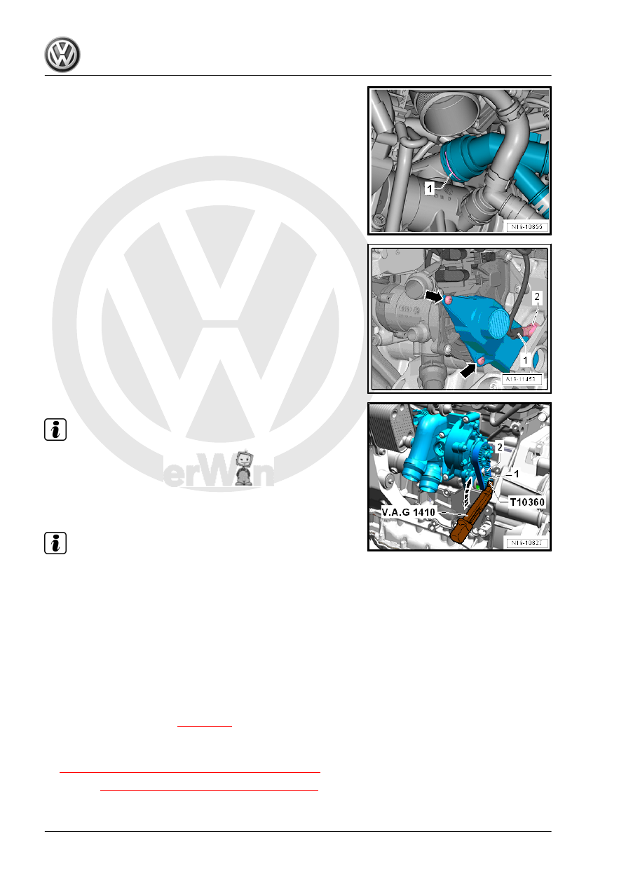
– Lift the clamp -1-, remove the upper coolant supports and set

them aside.

– Disconnect the connector -1- from the Oil Pressure Switch

-2-.

– Remove the bolts -arrows- and remove the toothed belt cover.

Note

The drive gear bolt has a left thread.

– Counterhold the vibration damper and remove the bolt from

the coolant pump the drive wheel -1- by loosening three turns.

Use Torque Wrench 1410 - VAG1410- and Torque Wrench

1331 Insert - Ring Wrench - 12mm - T10360- .

Note

If on vehicles with a manual transmission a starter bolt hinders

attaching the tool, remove the bolt approximately 15 mm.

– Remove the toothed belt -2-.
Installing
Install in reverse order of removal. Note the following:
– Replace the bolt for the drive wheel.
– Drive gear installation position: the collar on the drive gear

faces the transmission.

– Position the toothed belt and tighten the bolts.
– Fill with coolant. Refer to 

⇒ page 218

 .

Tightening Specifications
♦ Refer to

⇒ “2.1 Overview - Coolant Pump/Thermostat”, page 223

♦ Refer to 

⇒ “3.1 Overview - Air Filter Housing”, page 293

2.9

Engine Temperature Control Actuator -

N493- , Removing and Installing

Removing

Caution

This procedure contains mandatory replaceable parts. Refer

to component overview prior to starting procedure.

Mandatory Replacement Parts
♦ Seal - Engine Temperature Control Actuator
♦ O-rings - Engine Temperature Control Actuator
– Remove the coolant pump. Refer to

⇒ “2.7 Coolant Pump, Removing and Installing”, page 232

 .

– Remove the Throttle Valve Control Module - GX3- . Refer to

⇒ “4.5  Throttle Valve Control Module GX3 , Removing and

Installing”, page 309

 .

– Remove the coolant pipe from the intake manifold -arrows-.

– Lift the clamp -1-, and remove the coolant hoses.

– Remove the connector -1- from the Engine Temperature Con‐

trol Actuator - N493- .

– Remove the bolts -1 to 5-.
– Remove the Engine Temperature Control Actuator - N493-

from the centering pin and disconnect it from the engine oil

cooler.

Installing
Install in reverse order of removal. Note the following:

Note

Replace the seals and O-rings.

– Coat the new O-rings -4- with coolant.
– Make sure both centering pins are installed in the cylinder

block.

– Install the connection piece -2- into the engine oil cooler -1-.
– Push the Engine Temperature Control Actuator - N493- -3-

into the connection piece and onto the centering pins in the

cylinder block.

– Tighten the bolts for the Engine Temperature Control Actuator

- N493- . Refer to

⇒ Fig. ““ Engine Temperature Control Actuator -N493- - Tight‐

ening Specifications and Sequence”“ , page 225

 .

– Install the coolant pump. Refer to

⇒ “2.7 Coolant Pump, Removing and Installing”, page 232

 .

– Fill with coolant. Refer to 

⇒ page 218

 .

Tightening Specifications
♦ Refer to

⇒ “2.1 Overview - Coolant Pump/Thermostat”, page 223

 .

♦ Refer to 

⇒ “4.1 Overview - Intake Manifold”, page 296

 .

2.10

Engine Coolant Temperature Sensor -

G62- , Removing and Installing

Removing
• Engine is cold.
– Quickly open the coolant expansion tank cap -arrow- and re‐

lease any remaining pressure in the cooling system and then

close it again until it locks.

– Remove the air filter housing. Refer to

⇒ “3.2 Air Filter Housing, Removing and Installing”,

page 294

 .

– Loosen the hose clamp -2-.
– Remove bolt -1-, push the left air guide pipe left.

– Disconnect the connector -1-.

Note

Place a cleaning cloth underneath, to catch coolant leaking

out.

To prevent coolant loss, immediately insert the new Engine

Coolant Temperature Sensor - G62- in the connection.

– Remove the bolts -2-, and remove the Engine Coolant Tem‐

perature Sensor - G62- -3-.

Installing
Install in reverse order of removal. Note the following:

Note

Replace the O-rings.

– Check the coolant level. Refer to 

⇒ page 218

 .

Tightening Specifications
♦ Refer to

⇒ “2.3 Overview - Engine Coolant Temperature Sensor”, page

228

 .

♦ Refer to 

⇒ “3.1 Overview - Air Filter Housing”, page 293

 .

2.11

Engine Coolant Temperature Sensor on

Radiator Outlet - G83- , Removing and

Installing

Removing
• The engine is cold.


Content   ..  698  699  700  701   ..