Volkswagen Golf / Golf GTI / Golf Variant. Manual - part 694
1.1.2
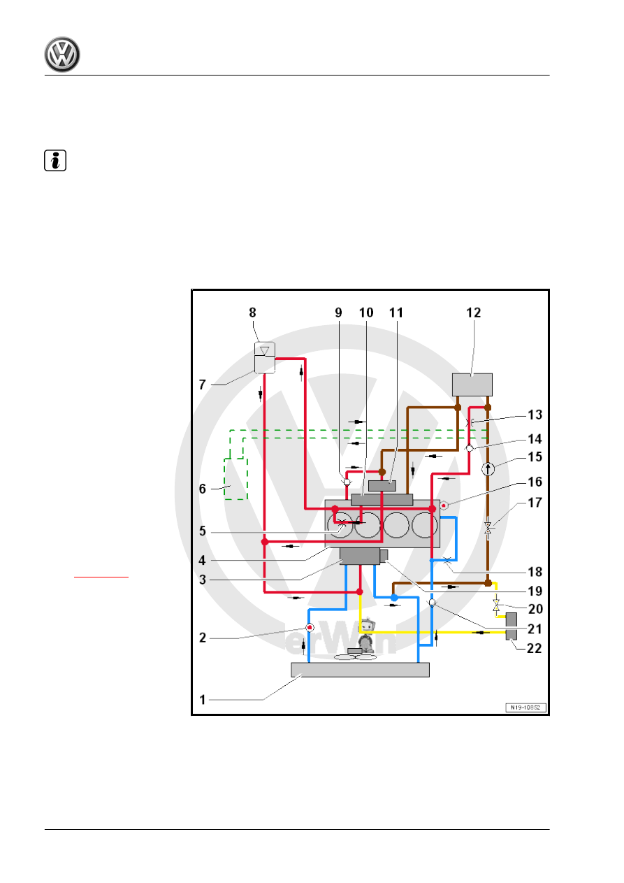
Coolant Hose Connection Diagram, Ve‐
hicles with a DSG
®
Transmission with‐
out Recirculation Pump - V55-
Note
♦
Blue = large coolant circuit.
♦
Red = small coolant circuit.
♦
Brown = heating circuit
♦
Yellow = transmission fluid cooling circuit
♦
The arrows show the coolant flow direction.
1 - Radiator
❑ Change the coolant af‐
ter replacing
2 - Engine Coolant Tempera‐
ture Sensor on Radiator Outlet
- G83-
3 - Engine Temperature Con‐
trol Actuator - N493-
4 - Cylinder Head/Cylinder
Block
❑ Change the coolant af‐
ter replacing
5 - Restrictor
6 - Parking Heater
❑ Vehicles versions
7 - Coolant Expansion Tank
8 - Coolant Expansion Tank
Cap
❑ Checking the pressure
relief valve. Refer to
9 - Check Valve
10 - Exhaust Manifold
❑ integrated in cylinder
head
11 - Turbocharger
12 - Heater Core for Heater
❑ Change the coolant af‐
ter replacing