Volkswagen Golf / Golf GTI / Golf Variant. Manual - part 683


  Index      Volkswagen     Volkswagen Golf / Golf GTI / Golf Variant - service repair manual 2013 year


Search            copyright infringement  


Content   ..  681  682  683  684   ..


Volkswagen Golf / Golf GTI / Golf Variant. Manual - part 683


For Exhaust Side
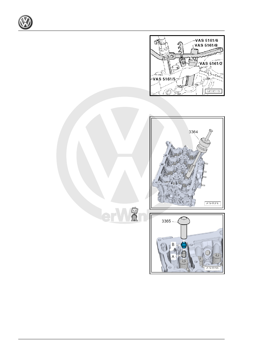
– Install the Retainer - VAS5161/6- with Forks M6/M8 Threaded

- VAS5161/5- in the outer thread of the Valve Cotter Tool Kit

- Guide Plate 19B - VAS5161/19B- .

– Press down the Assembly Cartridge - VAS5161/8A- and at the

same time turn the knurled thumb screw on the Assembly

Cartridge - VAS5161/8A- to the right until the points engage

in the valve retainers.

– Move the knurled thumb screw back and forth slightly. This

presses the valve retainers apart and captures them in the in‐

stallation cartridge.

– Release the Pressure Fork With Lever For Assembly Car‐

tridge - VAS5161/2- .

– Remove the Assembly Cartridge - VAS5161/8A- .

– Remove the valve stem seals using Puller - Valve Seal -

3364- .

Install Valve Stem Seals
– Place the plastic sleeve -A- that is attached to valve stem seals

-B- on valve stem.

– Lightly oil the valve stem seal.
– Slide the valve stem seal onto the plastic sleeve.
– Carefully press the valve stem seal onto the valve guide with

the Seal Installer - Valve Stem - 3365- .

– Remove plastic sleeve.
– Insert the valve spring and valve spring plate.
– Install the Valve Keeper Tool Kit - VAS5161A- as illustrated.

Intake Side

Exhaust Side

Note

If the valve retainers were removed from the assembly car‐

tridge, they must then be inserted into the Valve Insertion

Device - VAS5161/18- .

Press the Assembly Cartridge - VAS5161/8A- onto the inser‐

tion device from above and capture the valve retainers.

– Press the Valve Keeper Tool Kit Assembly Cartridge -

VAS5161/8- down with the Valve Keeper Tool Kit Pressure

Fork with Lever for Assembly Cartridge - VAS5161/2- and ro‐

tate the cartridge knurled thumb screw back and forth while

pulling up.

– Release the Pressure Fork with Lever for Assembly Cartridge

- VAS5161/2- with the knurled thumb screw pulled.

– Remove the Valve Keeper Tool Kit - VAS5161A- .
Assemble in reverse order of disassembly. Note the following:
– Install the camshafts. Refer to

⇒ “4.2 Camshaft, Removing and Installing”, page 136

 .

5

Intake and Exhaust Valves

⇒ “5.1 Valve Guides, Checking”, page 170

 .

⇒ “5.2 Valves, Checking”, page 170

 .

⇒ “5.3 Valve Dimensions”, page 170

 .

5.1

Valve Guides, Checking

Special tools and workshop equipment required
♦ Dial Gauge Holder - VW387-
♦ Dial Gauge - 0-10mm - VAS6079-
Test Sequence
– Insert the valve into guide. Valve stem end must be flush with

the guide. Due to differences in valve stem diameter, make

sure that only intake valves are used to check intake valve

guides, and only exhaust valves are used to check exhaust

valve guides.

– Determine tip clearance.
Wear Limit

Intake Valve Guide

Exhaust Valve Guide

0.80 mm

0.80 mm

Note

If wear limit is exceeded, measure using new valves. Replace

the cylinder head if the wear limit is still exceeded.

If the valve is replaced during a repair, use a new valve for

measurement.

5.2

Valves, Checking

– Check valves at stem and seating surface for traces of wear.
– If there are clear traces of wear, replace valve.

5.3

Valve Dimensions

Valve Dimensions

Note

Intake and exhaust valves must not be reworked. Only lapping is

permitted.

Dimension

Intake Valve

Exhaust Valve

Diameter

a

mm

33.85 ± 0.10

28.0 ± 0.1

Diameter

b

mm

5.98 ± 0.01

5.96 ± 0.01

c

mm

104.0 ± 0.2

101.9 ± 0.2

α

∠°

45

45

6

Special Tools

Special tools and workshop

equipment required
♦ Puller - Valve Seal - 3364-
♦ Seal Installer - Valve Stem

- 3365-

♦ Valve Keeper Tool Kit -

VAS5161A-

♦ Valve Cotter Tool Kit -

Guide Plate 19B -

VAS5161/19B-

♦ Engine And Transmission

Holder - VAS6095-

♦ Cylinder Head Tensioning

Device - VAS6419-


Content   ..  681  682  683  684   ..