Volkswagen Golf / Golf GTI / Golf Variant. Manual - part 681
Note
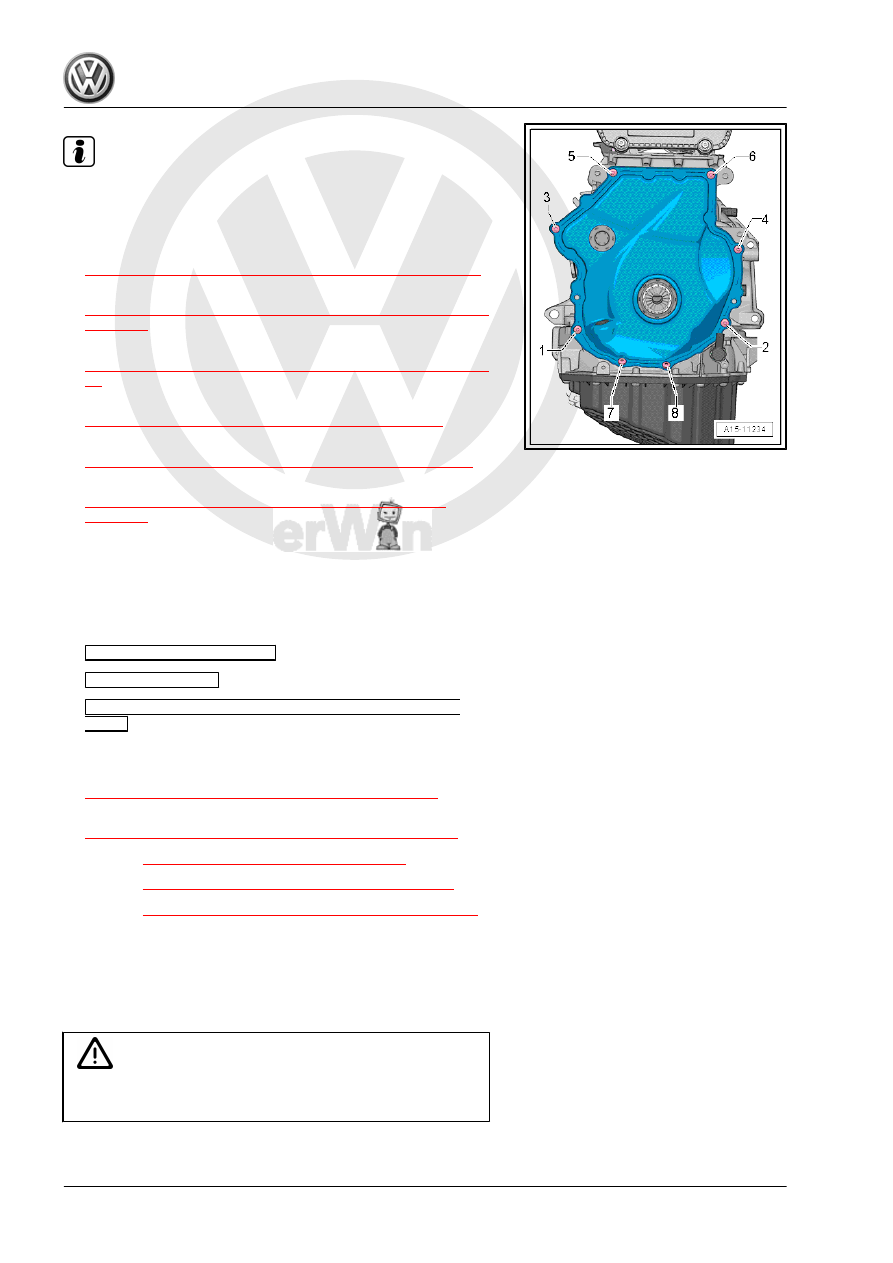
Tighten the bolts -1 and 4- with an additional turn after installing
the vibration damper. The bolts must be removed again to install
the vibration damper.
– Install the vibration damper. Refer to
⇒ “1.4 Vibration Damper, Removing and Installing”, page 47
– Install the upper timing chain cover. Refer to
⇒ “2.2.1 Upper Timing Chain Cover, Removing and Installing”,
– Install the ribbed belt tensioning damper. Refer to
⇒ “1.3 Ribbed Belt Tensioner, Removing and Installing”, page
– Install the ribbed belt. Refer to
⇒ “1.2 Ribbed Belt, Removing and Installing”, page 46
.
– Install the vacuum pump. Refer to
⇒ “1.4 Vacuum Pump, Removing and Installing”, page 100
– Install the high pressure pump. Refer to
⇒ “7.2 High Pressure Pump, Removing and Installing”,
The rest of the installation is performed in reverse order of re‐
moval, noting the following:
– After performing work on the chain drive the adaptation value
in the Engine Control Module (ECM) must be adapted. To do
this turn on the ignition and select the following menu items on
the Vehicle Diagnostic Tester :
♦
01 - Engine Electronics
♦
Guided Functions
♦
01 - Adaptation After Repair Work on the Chain
Drive
Tightening Specifications
♦ Refer to
⇒ “3.1 Overview - Camshaft Timing Chain”, page 114
.
♦ Refer to
⇒ “3.2 Overview - Balance Shaft Drive Chain”, page 116
♦ Refer to
⇒ “4.1 Overview - Valvetrain”, page 133
♦ Refer to
⇒ “3.1 Overview - Air Filter Housing”, page 293
.
♦ Refer to
⇒ “7.1 Overview - High Pressure Pump”, page 325
♦ Refer to ⇒ Body Exterior; Rep. Gr. 66 ; Noise Insulation;
Overview - Noise Insulation .
4.3
Camshaft Adjustment Valve 1 - N205- ,
Removing and Installing
Caution
This procedure contains mandatory replaceable parts. Refer
to component overview prior to starting procedure.