Volkswagen Golf / Golf GTI / Golf Variant. Manual - part 679
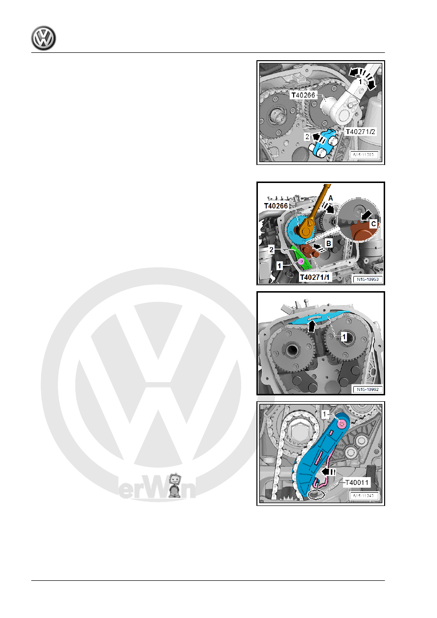
– Bolt the Camshaft Lock - Component 2 - T40271/2- to the cyl‐
inder head and slide into the splines on the chain sprocket in
the direction of -arrow 2-. Rotate the intake camshaft with the
Adapter - T40266- -1- if necessary.
– Install the Camshaft Lock - Component 1 - T40271/1- on the
cylinder head.
For the following steps a second technician is necessity.
– Hold the exhaust camshaft with the Adapter - T40266- in the
direction of -arrow A-. Remove the bolt -1- and guide the ten‐
sioning rail -2- downward. Turn the camshaft further in a
clockwise direction -arrow A- until the Camshaft Lock - Com‐
ponent 1 - T40271/1- can be slid into the chain sprocket
splines in direction of -arrow B-.
– Check the installation position -arrow C- of the Camshaft Lock
- Component 1 - T40271/1- .
– Remove the guide rail -1- by unlocking the latch -arrow- with
a screwdriver and pushing the guide rail forward.
– Press the oil pump chain tensioner bracket in direction of
-arrow- and lock with Locking Pin (3 pc.) - T40011- .
– Remove the bolt -1- and remove the chain tensioner.