Volkswagen Golf / Golf GTI / Golf Variant. Manual - part 628


  Index      Volkswagen     Volkswagen Golf / Golf GTI / Golf Variant - service repair manual 2013 year


Search            copyright infringement  


Content   ..  626  627  628  629   ..


Volkswagen Golf / Golf GTI / Golf Variant. Manual - part 628


5

Securing on Engine and Transmis‐

sion Holder

Special tools and workshop equipment required
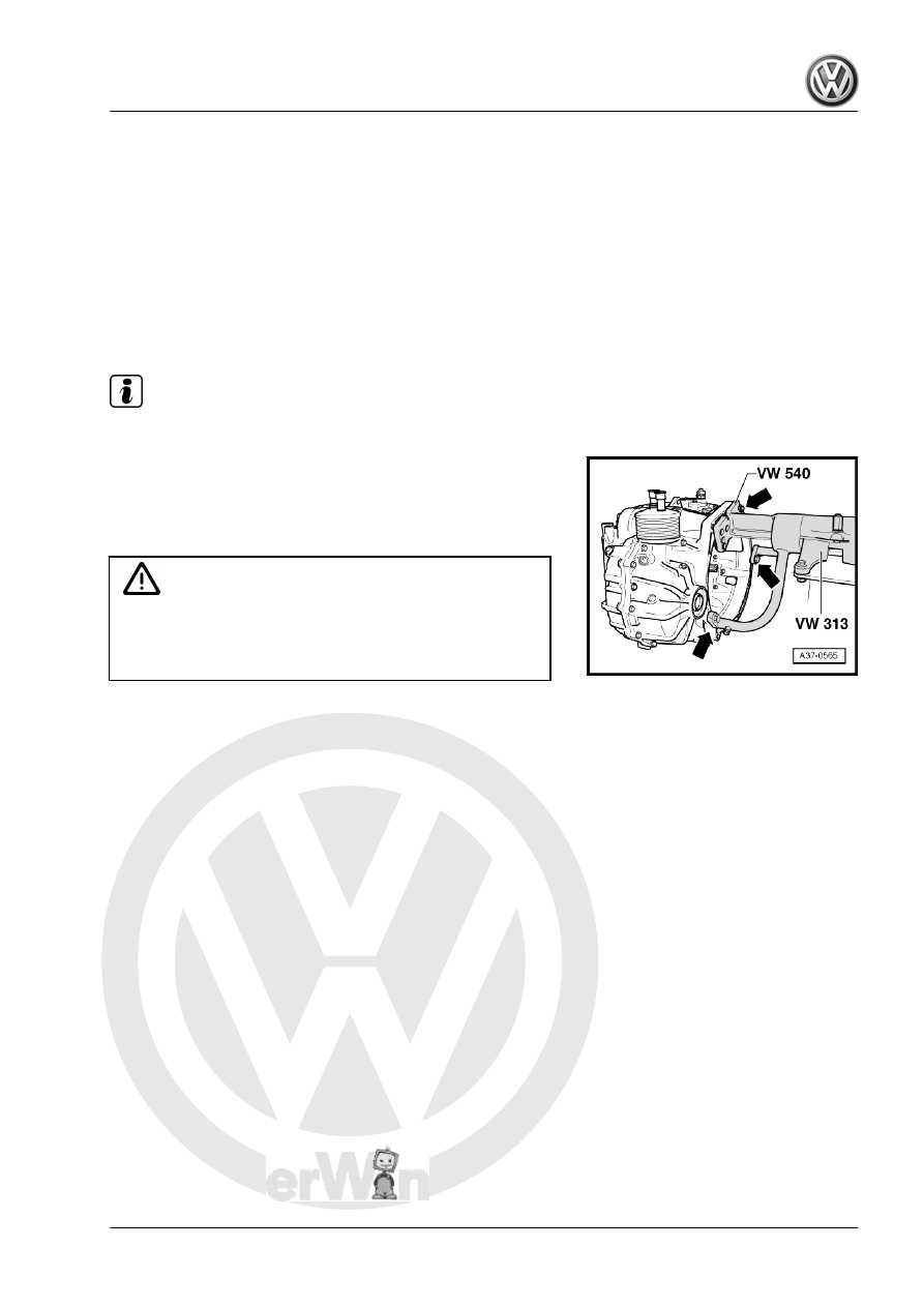
♦ Holding Fixture - VW313-
♦ Holding Fixture - VW540-
♦ Engine And Transmission Holder - VAS6095-
Remember there is oil in the transmission. Do not turn the trans‐

mission with the vents facing downward when transporting or

when it is on the assembly stand. The oil will leak out.

Note

Remove the bleed cap if necessary and use oil-tight plugs.

– Secure the transmission on the Holding Fixture - VW540-

-arrows-.

– Install the transmission using the Shop Crane - VAS6100- in

the Holding Fixture - VW313- or the Engine And Transmission

Holder - VAS6095- .

WARNING

Center of gravity of transmission is outside center of rotation

at holding fixture. To prevent back swing, a second technician

must hold transmission housing when rotating the transmis‐

sion on the Holding Fixture - VW313- .

6

ATF Circuit

⇒ “6.1 ATF Circuit Assembly Overview”, page 70
⇒ “6.2 ATF Cooler, Removing and Installing”, page 70

6.1

ATF Circuit Assembly Overview

1 - Transmission
2 - O-Rings

❑ Replace after removing

3 - ATF Cooler

❑ Removing and instal‐

ling. Refer to

⇒ “6.2 ATF Cooler, Re‐

moving and Installing”,

page 70

 .

4 - Bolt

❑ 20 Nm
❑ Quantity: 4, M8 x 25

6.2

ATF Cooler, Removing and Installing

Special tools and workshop equipment required
♦ Hose Clamps - Up To 25mm - 3094-
♦ Engine Bung Set - VAS6122-
♦ Hose Clip Pliers

Caution

This procedure contains mandatory replaceable parts. Refer

to component overview prior to starting procedure.

Mandatory Replacement Parts
♦ O-rings - ATF Cooler
Removing
– Move the selector lever into »P«.
– Remove the air filter housing. Refer to ⇒  Engine Mechanical,

Fuel Injection and Ignition; Rep. Gr.  24 ; Air Filter; Air Filter

Housing, Removing and Installing

– Remove the battery and the battery tray. Refer to ⇒  Electrical

Equipment; Rep. Gr.  27 ; Battery; Battery Tray, Removing and

Installing .

– Disconnect the selector lever cable on the retaining clip

-arrow-.

Note

Mark the ATF cooler coolant hoses to prevent confusing them

when installing them later.

The coolant system is under pressure when the engine is

warm.

Cover the cap on the reservoir with a cloth and open it carefully

before removing the coolant hoses.

– Clamp the coolant hoses with Hose Clamps - Up To 25mm -

3094- and remove them from the ATF cooler.

– Seal the coolant hoses and connections with plugs taken from

Engine Bung Set - VAS6122- .

– Remove the bolts -arrows- and take out the ATF cooler.
Installing
Install in reverse order of removal. Note the following:

Note

Always replace O-rings.

– Install the coolant hoses to the ATF cooler according the mark‐

ings made during the removal.

– Check the coolant level. Refer to ⇒  Engine Mechanical, Fuel

Injection and Ignition; Rep. Gr.  19 ; Cooling System/Coolant;

Coolant, Draining and Filling .

– Install the battery and the battery tray. Refer to ⇒  Electrical

Equipment; Rep. Gr.  27 ; Battery; Battery Tray, Removing and

Installing .

– Check the ATF level. Refer to

⇒ “7 Automatic Transmission Fluid”, page 73

 .

– Install the air filter housing. Refer to ⇒  Engine Mechanical,

Fuel Injection and Ignition; Rep. Gr.  24 ; Air Filter; Air Filter

Housing, Removing and Installing .

Tightening Specifications
♦ Refer to 

⇒ “6.1 ATF Circuit Assembly Overview”, page 70


Content   ..  626  627  628  629   ..