Volkswagen Golf / Golf GTI / Golf Variant. Manual - part 626


  Index      Volkswagen     Volkswagen Golf / Golf GTI / Golf Variant - service repair manual 2013 year


Search            copyright infringement  


Content   ..  624  625  626  627   ..


Volkswagen Golf / Golf GTI / Golf Variant. Manual - part 626


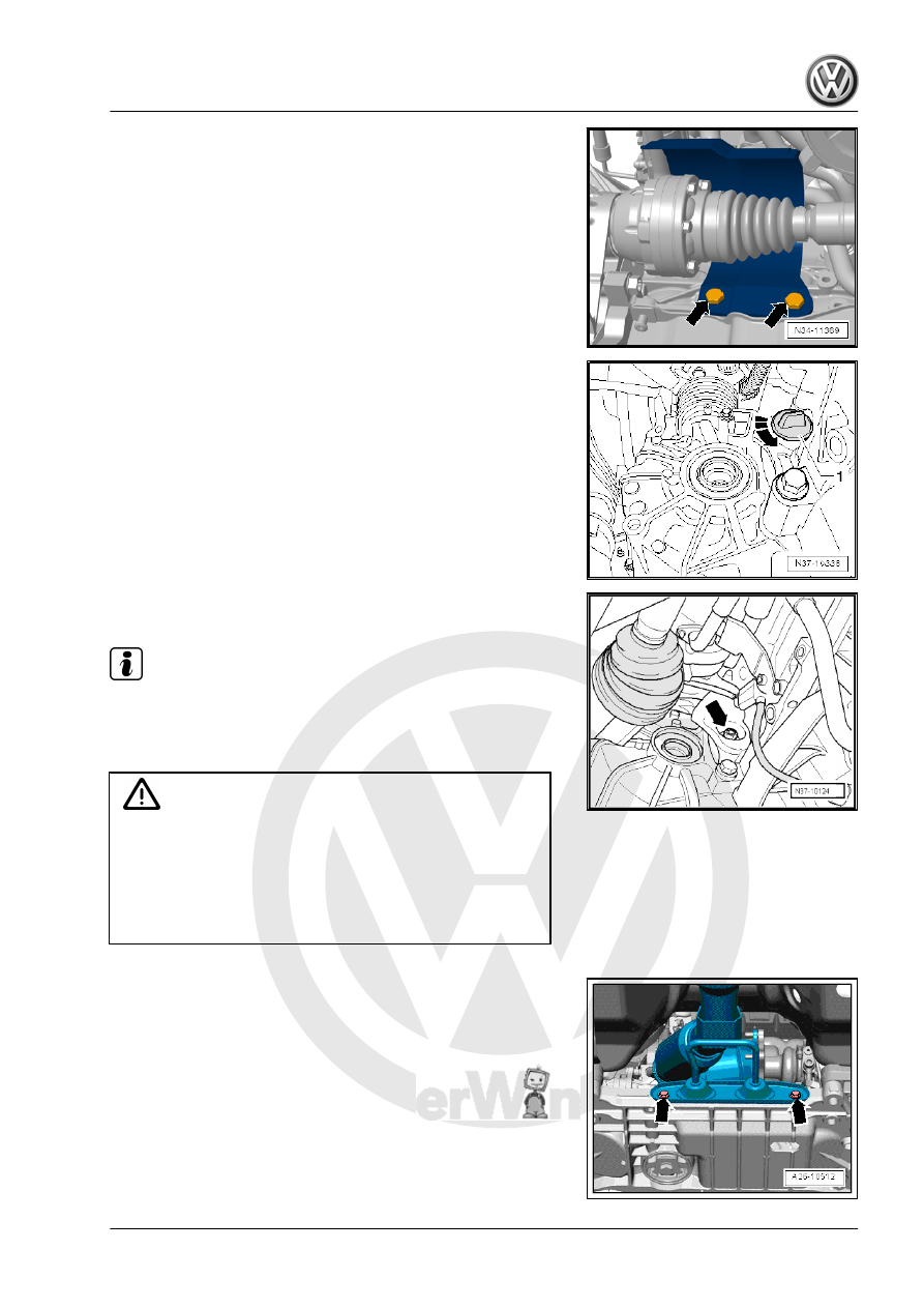
– Remove the heat shield (if equipped) above the right drive axle

-arrows-.

– Remove the left and right drive axles. Refer to ⇒  Suspension,

Wheels, Steering; Rep. Gr.  40 ; Drive Axle; Drive Axle, Re‐

moving and Installing .

– Turn the cap -1-, if present, in direction of -arrow- and remove.

– Remove the six converter nuts -arrow- with the Socket - Sw15

- V/175- .

Note

Carefully rotate the engine further!

The torque converter will be pulled out when the transmission

is separated from the engine if all nuts are not removed!

Caution

There is a danger of causing damage to the decoupling ele‐

ment.

♦ Do not bend the decoupling element more than 10°.
♦ Do not load the decoupling element.
♦ Do not damage the wire mesh on the decoupling element.

– Remove the bracket bolts -arrows- for the exhaust system on

the subframe.

– Disconnect the exhaust system at the clamping sleeve

-arrow-. Refer to ⇒  Engine Mechanical, Fuel Injection and Ig‐

nition; Rep. Gr.  26 ; Exhaust Pipes/Mufflers; Overview -

Muffler .

– Remove bolts -1 through 3- and remove pendulum support.

– Loosen the hose clamps -arrows- and remove the left charge

air hose -A-. Refer to ⇒  Engine Mechanical, Fuel Injection and

Ignition; Rep. Gr.  21 ; Charge Air System; Overview - Charge

Air System .

– Remove the bolts -2- that attach the transmission mount to the

transmission bracket -A- and the bolts -1- that attach the trans‐

mission bracket to the transmission.

– Remove the transmission bracket -A-. To do this slightly lower

the engine with the transmission using the Engine Support

Bridge - 10-222A- spindle.

Four turns should be sufficient.
– Remove the lower bolts between the engine and the trans‐

mission.

Note

The rear connecting hose between the engine and transmission,

in the area of the right drive axle remains installed.

– Place the Transmission Support - 3282- on the Engine and

Gearbox Jack - VAS6931- or Engine/Gearbox Jack -

VAG1383A- .

Install the Transmission Support - 3282- as Follows with the

Mounting Element on the Transmission:
• The Engine and Gearbox Jack with Transmission Support is

positioned under the transmission -1- so that the spindle

-arrow A- points forward in the direction of travel.

• The spindle -arrow B- points in the direction of travel to the left.
• The Mounts -2- are positioned as shown in the illustration in

the oil pan surrounding groove.

• The Pins -3- lock in the recess on the front right of the trans‐

mission.

– Install the Engine Support Bridge - Engine Support 29 -

10-222A/29- into the rear hole for the pendulum support bolt

on the transmission -1-.

– Support the transmission with the Engine and Gearbox Jack

by carefully lifting.

– Remove the last bolt -arrow B- for the engine to the transmis‐

sion. This bolt can be removed with for example the Socket -

Xzn 14 - T10061- .

Note

Ignore the bolt -arrow A-.

– While pressing the torque converter off the drive plate, sepa‐

rate the transmission from the engine.

– Guide the transmission past the subframe when lowering it.

Adjust the Transmission Support - 3282- slightly, if necessary.

Note

The connector on the transmission must not be damaged

when removing and installing transmission. Replace the wiring

harness in the transmission if the connector gets damaged.

Refer to

⇒ “2.4 Solenoid Valve and Sensor Wiring Harness, Removing

and Installing”, page 99

 .

Be careful of the torque converter. It must be removed together

with the transmission. Secure the torque converter for exam‐

ple with a wire -A- to prevent it from falling out.

The illustration of the transmission may differ from the original

part.

3.2

Transmission, Installing

Note

For the special tool needed and mandatory replacement parts.

Refer to 

⇒ “3.1 Transmission, Removing”, page 43

 .

Install in reverse order of removal. Note the following:
– Make sure the alignment sleeves are pressed into the engine

flange.

– Make sure the intermediate plate fits correctly between the

engine and the transmission. The plate must contact the en‐

gine along the entire perimeter. If it is above the engine, then

it is not hooked into the cylinder block correctly.

– Make sure the torque converter is installed correctly. Refer to

⇒ “1.2 Torque Converter, Removing and Installing”, page 14

 .

It must be easy turn easily by hand and the entire circumfer‐

ence must be equally deep inside the transmission.

– Carefully raise the transmission with the Engine and Gearbox

Jack - VAS6931- or Engine/Gearbox Jack - VAG1383A- and

bring it into the installation position using the Transmission

Support - 3282- .

– Insert transmission without pinching any lines.

Note

Engine and transmission must be brought together by hand

until both flanges touch all around!

If this is not the case, adjust the Transmission Support until

the engine and transmission are in alignment.

While the transmission is guided onto the engine, carefully turn

the engine further! Hold the starter ring gear steady from the

outside with a screwdriver. When installing torque converter

threaded pins are located in the drive plate holes.

– Fasten the transmission on the engine and the torque con‐

verter on the drive plate.


Content   ..  624  625  626  627   ..