Volkswagen Golf / Golf GTI / Golf Variant. Manual - part 624


  Index      Volkswagen     Volkswagen Golf / Golf GTI / Golf Variant - service repair manual 2013 year


Search            copyright infringement  


Content   ..  622  623  624  625   ..


Volkswagen Golf / Golf GTI / Golf Variant. Manual - part 624


– Place the Transmission Support - 3282- on the Engine and

Gearbox Jack - VAS6931- or Engine/Gearbox Jack -

VAG1383A- .

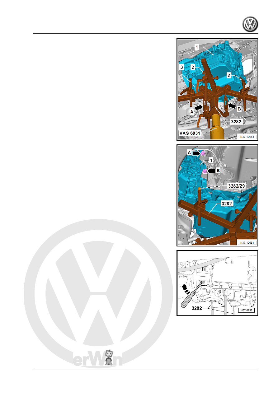
Install the Transmission Support - 3282- as follows with the

Mounting Element on the transmission:
• The Engine and Gearbox Jack with Transmission Support is

positioned under the transmission -1- so that the spindle

-arrow A- points forward in the direction of travel.

• The spindle -arrow B- points in the direction of travel to the left.
• The Mounts -2- are positioned as shown in the illustration in

the oil pan surrounding groove.

• The Pins -3- lock in the recess on the front right of the trans‐

mission.

– Install the Transmission Support - Pins 29 - 3282/29- into the

rear hole for the pendulum support bolt on the transmission

-1-.

– Support the transmission with the Engine and Gearbox Jack

by carefully lifting.

– Remove the last bolts for the -arrow A- and -arrow B- for the

engine to the transmission. These bolts can be removed with

for example the Socket - Xzn 14 - T10061- .

– While pressing the torque converter off the drive plate, sepa‐

rate the transmission from the engine.

– Guide the transmission past the subframe when lowering it.

Adjust the Transmission Support - 3282- slightly, if necessary.

Note

The connector on the transmission must not be damaged

when removing and installing transmission. Replace the wiring

harness in the transmission if the connector gets damaged.

Refer to

⇒ “2.4 Solenoid Valve and Sensor Wiring Harness, Removing

and Installing”, page 99

 .

Be careful of the torque converter. It must be removed together

with the transmission. Secure the torque converter for exam‐

ple with a wire -A- to prevent it from falling out.

The torque converter and transmission in the illustration may

differ from the Original Part.

3.1.2

Transmission, Removing, Vehicles with

1.8L - 125 kW Engine

Short Description
The transmission is removed downward separately. The engine

remains in the vehicle.
Remove the battery, the battery tray, the engine cover and the air

filter housing »from above«. Engine with transmission are then

supported so that the left subframe mount can be removed.
Remove the noise insulation »from underneath«. Remove the

drive axles from the transmission and then remove the drive

axles. Lower the transmission with the transmission jack.
The subframe is not removed.
Special tools and workshop equipment required
♦ Engine Support Bridge - 10-222A-
♦ Engine Support Bridge - Engine Support 29 - 10-222A/29-
♦ Engine Support Bridge - Engine Support 18 - 10-222A/18-
♦ Engine/Gearbox Support Shackle (2 pc.) - 10-222A/12- (quan‐

tity 2)

♦ Transmission Support - Pins 29 - 3282/29-
♦ Transmission Support - 3282-
♦ Hose Clamps - Up To 25mm - 3094-
♦ Engine Support - Basic Set Square Pipe - T40091/1- (quantity

2)

♦ Engine Support - Basic Set Movable Joint - T40091/3- (quan‐

tity 2)

♦ Engine Support - Supplement Kit Spindle - T40093/3- (quan‐

tity 2) from the Engine Support - Supplement Kit - T40093A-

♦ Engine Support Brackets - T40093/3-6- (quantity 2)
♦ Engine Bung Set - VAS6122-
♦ Engine and Gearbox Jack - VAS6931- or Engine/Gearbox

Jack - VAG1383A-

♦ Socket - Sw15 - V/175-

♦ Hose Clip Pliers
♦ Engine Support Bridge - Engine Support 4 - 10-222A/4-
♦ Insert Tool - 18mm - T10179-
♦ Engine Support Bridge - Special Hook (2 pc.) - 10-222A/20-
♦ Engine Support Brackets - T40093/3-6-
♦ Socket - Xzn 14 - T10061-

Caution

This procedure contains mandatory replaceable parts. Refer

to component overview prior to starting procedure.

Mandatory Replacement Parts
♦ Bolts - Pendulum Support
♦ Bolts - Transmission Mount to Transmission Bracket
♦ Bolts - Transmission Bracket to Transmission
♦ Bolts - Engine to Transmission
Tool Development
– If the adapter for Engine Support Bridge - Engine Support 4 -

10-222A/4- does not have the indicated holes -arrow- shown

they must be added.

• Dimension -a- = 225 mm
• Hole diameter = 12.5 mm
Removing

Note

Pay attention to 

⇒ “3 Repair Information”, page 4

 .

Reinstall cable ties that were loosened or cut off during re‐

moval at same locations during installation.

– With the vehicle still standing on its wheels, loosen the left and

right twelve-point bolt -arrow- a maximum 90°, otherwise the

wheel bearing will get damaged. Refer to ⇒  Suspension,

Wheels, Steering; Rep. Gr.  40 ; Drive Axle; Drive Axle Threa‐

ded Connection, Loosening and Tightening .

Note

Do not place vehicle on floor after loosening bolt.

– Slightly lift the vehicle, all four take-up points of lifting platform

at same height.

– Move the selector lever into »P«.
– Disconnect the battery. Refer to ⇒  Electrical Equipment; Rep.

Gr.  27 ; Battery; Battery, Disconnecting and Connecting .

– Remove the engine cover. Refer to ⇒  Engine Mechanical,

Fuel Injection and Ignition; Rep. Gr.  10 ; Engine Cover; Engine

Cover, Removing and Installing .

– Remove the air filter housing. Refer to ⇒  Engine Mechanical,

Fuel Injection and Ignition; Rep. Gr.  24 ; Air Filter; Air Filter

Housing, Removing and Installing

– Remove the battery and the battery tray -1-. Refer to ⇒  Elec‐

trical Equipment; Rep. Gr.  27 ; Battery; Battery Tray, Remov‐

ing and Installing .

– Pry the selector lever cable -1- off the selector lever -3-, for

example, using a wrench.

The adjusting screw -2- must not be loosened.
– Disconnect the connector from the Multifunction Transmission

Range Switch - F125- .


Content   ..  622  623  624  625   ..