Volkswagen Golf / Golf GTI / Golf Variant. Manual - part 622


  Index      Volkswagen     Volkswagen Golf / Golf GTI / Golf Variant - service repair manual 2013 year


Search            copyright infringement  


Content   ..  620  621  622  623   ..


Volkswagen Golf / Golf GTI / Golf Variant. Manual - part 622


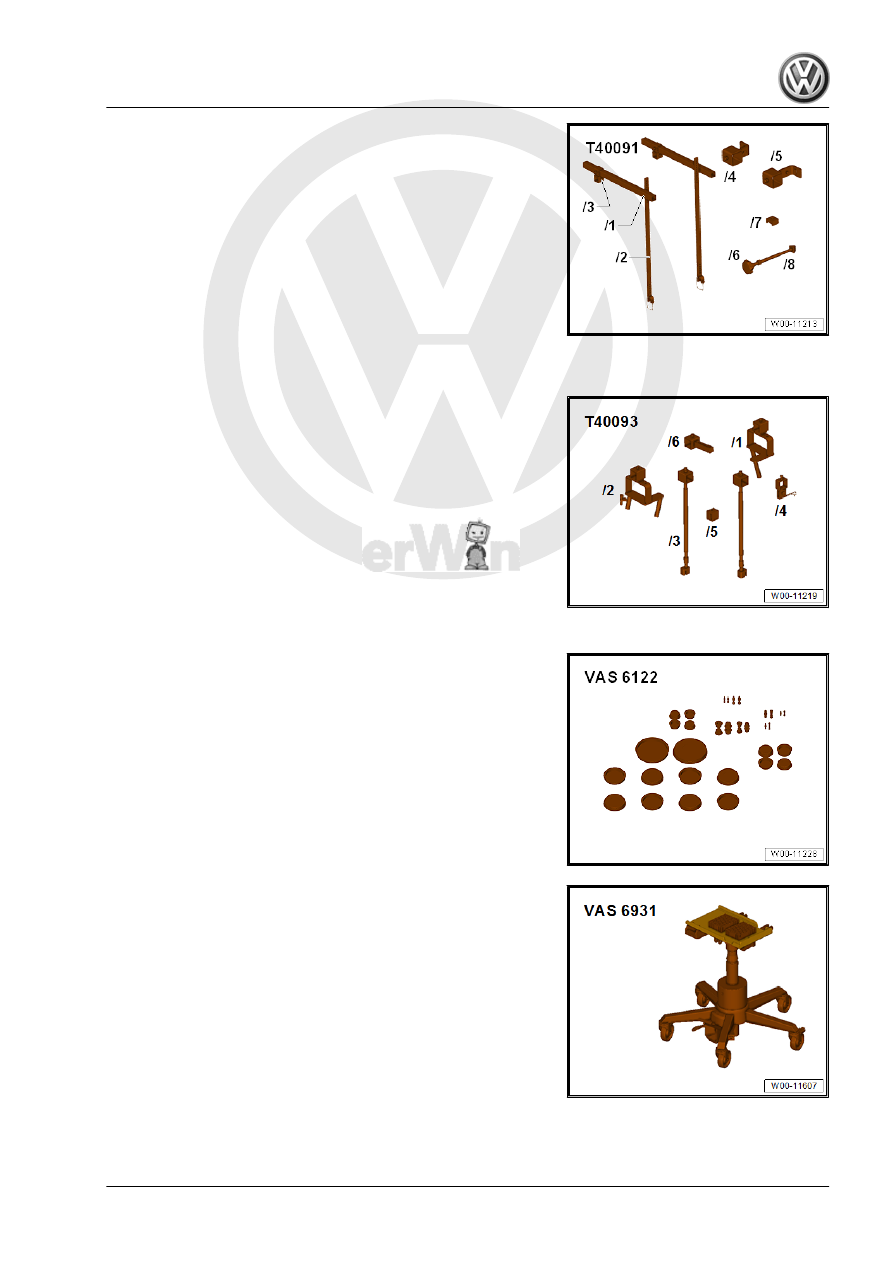
♦ Engine Support - Basic Set Square Pipe - T40091/1- (quantity

2)

♦ Engine Support - Basic Set Movable Joint - T40091/3- (quan‐

tity 2)

♦ Engine Support - Supplement Kit Spindle - T40093/3- (quan‐

tity 2) from the Engine Support - Supplement Kit - T40093A-

♦ Engine Support Brackets - T40093/3-6- (quantity 2)
♦ Engine Bung Set - VAS6122-

♦ Engine and Gearbox Jack - VAS6931- or Engine/Gearbox

Jack - VAG1383A-

♦ Socket - Sw15 - V/175-

♦ Hose Clip Pliers
Tool Development
– If the adapter for Engine Support Bridge - Engine Support 4 -

10-222A/4- does not have the indicated holes -arrow- shown

they must be added.

• Dimension -a- = 225 mm
• Hole diameter = 12.5 mm
Removing

Note

Pay attention to 

⇒ “3 Repair Information”, page 4

 .

Reinstall cable ties that were loosened or cut off during re‐

moval at same locations during installation.

– With the vehicle still standing on its wheels, loosen the left and

right twelve-point bolt -arrow- a maximum 90°, otherwise the

wheel bearing will get damaged. Refer to ⇒  Suspension,

Wheels, Steering; Rep. Gr.  40 ; Drive Axle; Drive Axle Threa‐

ded Connection, Loosening and Tightening .

Note

Do not place vehicle on floor after loosening screw.

– Slightly lift the vehicle, all four take-up points of lifting platform

at same height.

– Move the selector lever into »P«.
– Disconnect the battery. Refer to ⇒  Electrical Equipment; Rep.

Gr.  27 ; Battery; Battery, Disconnecting and Connecting .

– Remove the air filter housing. Refer to ⇒  Engine Mechanical,

Fuel Injection and Ignition; Rep. Gr.  24 ; Air Filter; Air Filter

Housing, Removing and Installing

– Remove the battery and the battery tray -1-. Refer to ⇒  Elec‐

trical Equipment; Rep. Gr.  27 ; Battery; Battery Tray, Remov‐

ing and Installing .

– Pry the selector lever cable -1- off the selector lever -3-, for

example, using a wrench.

The adjusting screw -2- must not be loosened.
– Disconnect the connector from the Multifunction Transmission

Range Switch - F125- .

– Disengage the selector lever cable -1- from the bracket -2- clip

-3-.

– Remove the cable bracket -4- from the transmission to do this

remove the bolts -arrows-.

Note

Do not remove the clip -5-.

Do not bend or kink the selector lever cable.

– Removing starter. Refer to ⇒  Electrical Equipment; Rep. Gr. 

27 ; Starter; Starter, Removing and Installing .

– Place lint-free cloth on to ATF cooler and transmission to ab‐

sorb exiting coolant.

Note

Mark the ATF cooler coolant hoses to prevent confusing them

when installing them later.

The coolant system is under pressure when the engine is

warm.

Cover the cap on the reservoir with a cloth and open it carefully

before removing the coolant hoses.

– Clamp the coolant hoses with Hose Clamps - Up To 25mm -

3094- and remove them from the ATF cooler.

– Seal the coolant hoses and connections with plugs taken from

Engine Bung Set - VAS6122- .

– Remove the upper transmission bolts -arrows- to the engine,

for example, with a 12-point double joint socket insert -A-.

– Remove the filler tube for the windshield washer system wash‐

er fluid reservoir. Refer to ⇒  Electrical Equipment; Rep. Gr. 

92 ; Windshield Washer System; Washer Fluid Reservoir, Re‐

moving and Installing .

– Insert the Engine Support Bridge - Engine Support 29 -

10-222A/29- between the fender bolting edge and the fender

bolting plate underneath it on both sides of the vehicle.

♦ Engine Support Bridge - Engine Support 29 - 10-222A/29- in‐

stallation position:

Adapter -L- is installed on the right side of the vehicle:
– The Adapter -arrow- locks in the opening on the fender.
The Adapter -R- is installed on the left side of the vehicle:
– The Adapter -arrow- locks in the opening on the fender.


Content   ..  620  621  622  623   ..