Volkswagen Golf / Golf GTI / Golf Variant. Manual - part 617


  Index      Volkswagen     Volkswagen Golf / Golf GTI / Golf Variant - service repair manual 2013 year


Search            copyright infringement  


Content   ..  615  616  617  618   ..


Volkswagen Golf / Golf GTI / Golf Variant. Manual - part 617


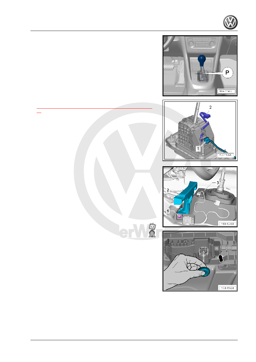
– Move the selector lever into “P”.

– Remove the selector lever handle. Refer to

⇒ “2.6 Selector Lever Handle, Removing and Installing”, page

33

 . Disconnect the connector -2- from the cover while doing

this.

– Disconnect the connector -1- from the selector mechanism to

the vehicle wiring harness.

– Remove the center console. Refer to ⇒  Body Interior; Rep.

Gr.  68 ; Center Console; Overview - Center Console .

– Remove the air guide channel from the center console. Refer

to ⇒  Heating, Ventilation and Air Conditioning; Rep. Gr.  87 ;

Air Routing; Overview - Air Routing and Air Distribution in Pas‐

senger Compartment .

– Remove the bracket -2-, to do this remove the left and right

bolts -1-.

– Position the selector lever on the selector mechanism in the

“N” position. The cable can only be loosened in this position.

– Remove the center tunnel heat shield under the selector

mechanism. Refer to ⇒  Body Exterior; Rep. Gr.  66 ; Molding/

Trim/Extensions/Trim Panels; Floor Heat Shield, Removing

and Installing .

– Remove the plugs, and remove the clip -arrow-.
Replace the clip after removing.

– Insert a large screwdriver in the groove on the locking mech‐

anism and turn 90° in the direction of -arrow-.

– Remove the cable from the selector mechanism.
– Remove the bracket -A-, if equipped.
– Remove the nuts -arrows- in the vehicle interior.

– Remove the selector mechanism -B- with the gearshift hous‐

ing downward.

Installing
Install in reverse order of removal. Note the following:
A second technician will be needed for inserting the selector lever

cable from the passenger compartment into the engine compart‐

ment.

Note

Do not bend or kink the selector lever cable.

Do not lubricate the selector lever cable.

After installation, the selector lever cable movement must be

checked and adjusted.

• The selector mechanism selector lever is in the “N” position.

The cable can only be locked in this position.

– Guide the cable in the selector mechanism until it is visible

through the locking mechanism -arrow-.

– Turn the locking mechanism in the direction of -arrow- 90° with

a large screwdriver.

– The cable is correctly locked when the grooves on the locking

mechanism are at a right angle to the cable.

– Install new clip -arrow- and replace the plugs.
– Install the heat shield under the selector mechanism. Refer to

⇒  Body Exterior; Rep. Gr.  66 ; Molding/Trim/Extensions/Trim

Panels; Floor Heat Shield, Removing and Installing .

– Install the bracket -2- if equipped. Refer to ⇒  Body Interior;

Rep. Gr.  68 ; Center Console; Center Console, Removing and

Installing .

– Install the air guide channel from the center console. Refer to

⇒  Heating, Ventilation and Air Conditioning; Rep. Gr.  87 ; Air

Routing; Overview - Air Routing and Air Distribution in Pas‐

senger Compartment .

– Install the center console. Refer to ⇒  Body Interior; Rep. Gr. 

68 ; Center Console; Center Console, Removing and Instal‐

ling .

– Install the selector lever handle. Refer to

⇒ “2.6 Selector Lever Handle, Removing and Installing”, page

33

 .

– Selector lever cable, adjusting. Refer to

⇒ “2.4 Selector Lever Cable, Checking and Adjusting”,

page 30

 .

– Check the selector mechanism. Refer to

⇒ “2.8 Gearshift Mechanism, Checking”, page 36

Tightening Specifications
♦ Refer to 

⇒ “2.1 Overview - Selector Mechanism”, page 19

2.3

Selector Lever Cable, Removing and In‐

stalling

Caution

This procedure contains mandatory replaceable parts. Refer

to component overview prior to starting procedure.

Mandatory Replacement Parts
♦ Clip - Selector Lever Cable to the Cable Bracket
♦ Clip - Selector Lever Cable to the Selector Mechanism
♦ Plug - Selector Mechanism
– Remove the air filter housing. Refer to ⇒  Engine Mechanical,

Fuel Injection and Ignition; Rep. Gr.  24 ; Air Filter; Air Filter

Housing, Removing and Installing

– Disengage the selector lever cable -1- from the bracket -2- clip

-3-.

Use pliers to remove the clip -5- from the cable bracket -4-. Do

not use a sharp-edged lever. Otherwise the selector lever cable

could get damaged.

Note

Always replace the clip on the selector lever cable.

It is better to remove the cable bracket -4- together with the

selector lever cable -1- from the transmission -arrow-.

If the selector lever cable is replaced, the cable bracket -4-

must be replaced.

– Pry the selector lever cable -1- off the selector lever -3-, for

example, using a wrench.

The adjusting screw -2- must not be loosened.

Caution

Danger of damaging the selector lever cable.

♦ Push the selector lever cable to the rear and out of the

cable bracket. The selector lever cable is guided out of the

cable bracket when removing the selector mechanism.

– Lift the vehicle.
– Remove the center tunnel heat shield under the selector

mechanism. Refer to ⇒  Body Exterior; Rep. Gr.  66 ; Molding/

Trim/Extensions/Trim Panels; Floor Heat Shield, Removing

and Installing .

– Remove the plugs, and remove the clip -arrow-.
Replace the clip after removing.


Content   ..  615  616  617  618   ..