Volkswagen Golf / Golf GTI / Golf Variant. Manual - part 593


  Index      Volkswagen     Volkswagen Golf / Golf GTI / Golf Variant - service repair manual 2013 year


Search            copyright infringement  


Content   ..  591  592  593  594   ..


Volkswagen Golf / Golf GTI / Golf Variant. Manual - part 593


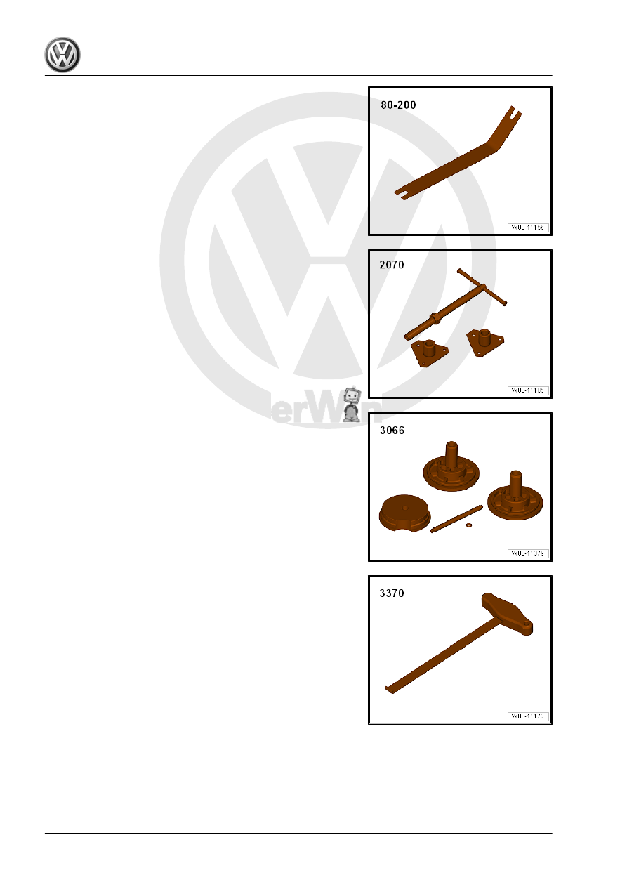
♦ Pry Lever - 80-200-

♦ Spring Strut Compressor - 2070-

♦ Spindle from the Seal Installer - Driver Set - 3066- or M8 x 105

bolt

♦ or the equivalent equipment, Backrest Panel Tool - 3370-

♦ Sealing Compound - AMV 188 200 03-
♦ M8 x 100 mm stud bolt

35 – Gears, Shafts

1

Input Shaft

⇒ “1.1 Overview - Input Shaft”, page 141
⇒ “1.2 Input Shaft, Disassembling and Assembling”, page 143
⇒ “1.3 Input Shaft, Adjusting”, page 148
⇒ “1.4 Input Shaft Seal, Replacing”, page 152

1.1

Overview - Input Shaft

Note

Pay attention to the Parts Catalog and to the Technical data when installing new gear wheels or a new input

shaft. Refer to 

⇒ “4 Technical Data”, page 6

 .

The input shaft must be adjusted because the position of the tapered roller bearing is affected when parts

are replaced. Pay attention to the adjustment overview. Refer to 

⇒ “3 Adjustment Overview”, page 198

 .

Replace both tapered roller bearings together.

Wearing safety gloves, warm the inner race/tapered roller bearing, the gear wheels and the synchronizer

hubs to approximately 100 °C (212 °F) using an Inductive Heat Unit - VAS6414- before installing them.

1 - Clutch Housing
2 - Outer Race/Tapered Roller

Bearing

❑ Removing. Refer to

⇒ Fig. ““Removing the

Outer Race/Tapered

Roller Bearing”“ ,

page 144

❑ Installing. Refer to

⇒ Fig. ““Installing the

Outer Race/Tapered

Roller Bearing”“ ,

page 144

3 - Inner Race / Tapered Roller

Bearing

❑ Removing. Refer to

⇒ Fig. ““Removing the

Inner Race/Tapered

Roller Bearing”“ ,

page 144

❑ Installing. Refer to

⇒ Fig. ““Installing the In‐

ner Race/Tapered Roll‐

er Bearing”“ , page 145

4 - Input Shaft

❑ Adjusting. Refer to

⇒ “1.3 Input Shaft, Ad‐

justing”, page 148

 .

5 - 3rd Gear Wheel

❑ Installed position: shoul‐

der faces 4th gear

❑ Removing. Refer to

⇒ Fig. ““Removing the

3rd Gear Wheel”“ , page

145

❑ Installing. Refer to 

⇒ Fig. ““Installing 3rd Gear Wheel”“ , page 145

6 - Circlip

❑ Replace after removing

7 - 4th Gear Wheel

❑ Removing with the outer race/tapered roller bearing and sleeve. Refer to

⇒ Fig. ““Removing the 4th Gear Wheel with the Tapered Roller Bearing and Sleeve”“ , page 145

❑ Installing. Refer to 

⇒ Fig. ““Removing 4th Gear Wheel”“ , page 146

❑ The shoulder faces 3rd gear

8 - Inner Race / Tapered Roller Bearing

❑ Removing with 4th gear wheel and sleeve. Refer to

⇒ Fig. ““Removing the 4th Gear Wheel with the Tapered Roller Bearing and Sleeve”“ , page 145

❑ Installing. Refer to 

⇒ Fig. ““Installing the Inner Race/Tapered Roller Bearing”“ , page 146

9 - Thrust Washer
10 - Outer Race/Tapered Roller Bearing

❑ Removing. Refer to 

⇒ Fig. ““Installing the Outer Race/Tapered Roller Bearing”“ , page 147

❑ Installing. Refer to 

⇒ Fig. ““Installing the Outer Race/Tapered Roller Bearing”“ , page 147

11 - Shim

❑ Selecting thickness. Refer to 

⇒ “1.3 Input Shaft, Adjusting”, page 148

 .

12 - Transmission Housing
13 - Sleeve

❑ For the 5th gear needle bearing
❑ Pressing off with 4th gear drive gear and the inner race/tapered roller bearing. Refer to

⇒ Fig. ““Removing the 4th Gear Wheel with the Tapered Roller Bearing and Sleeve”“ , page 145

❑ Installing. Refer to 

⇒ Fig. ““Installing the Needle Bearing Sleeve”“ , page 146

❑ Mount before installing the thrust washer -item 9- 

⇒ Item 9 (page 142)

 .

14 - Needle Bearing

❑ For 5th gear

15 - 5th Gear Wheel
16 - 5th Gear Synchronizer Ring

❑ With cast locking pieces. Refer to

⇒ Fig. ““5th Gear Synchronizer Ring with Cast Locking Pieces”“ , page 116

❑ Checking for wear. Refer to 

⇒ Fig. ““Checking 5th Gear Synchronizer Ring”“ , page 116

17 - Spring

❑ Installation position. Refer to

⇒ Fig. ““5th Gear Locking Collar/Synchronizer Hub Assembly”“ , page 147

 and

⇒ Fig. ““Installation of Offset Springs -A- ”“ , page 148

18 - Locking Pieces (quantity: 3)

❑ Installed position. Refer to 

⇒ Fig. ““5th Gear Synchronizing”“ , page 147

19 - 5th Gear Synchronizer Hub

❑ Remove. Refer to 

⇒ “5.10 Transmission Housing Cover and 5th Gear, Removing”, page 101

20 - 5th Gear Locking Collar

❑ Remove with 5th gear synchronizer hub. Refer to

⇒ “5.10 Transmission Housing Cover and 5th Gear, Removing”, page 101

21 - Plate Spring

❑ Installed position. Refer to

⇒ Fig. ““Installed Position of Plate Springs for 5th Gear Synchronizer Hub and Gear Securing Bolts”“ ,

page 117

22 - Bolt

❑ Replace after removing
❑ Holds in position with the adapter on the plate spring bolt head. Refer to

⇒ Fig. ““Installed Position of Plate Springs for 5th Gear Synchronizer Hub and Gear Securing Bolts”“ ,

page 117

❑ Removing and installing. Refer to

⇒ “5.10 Transmission Housing Cover and 5th Gear, Removing”, page 101

 .

❑ Tightening specification. Refer to

⇒ “5.3 Overview - Transmission Housing Cover and 5th Gear”, page 93

 .

1.2

Input Shaft, Disassembling and Assem‐

bling

Special tools and workshop equipment required
♦ Press Piece - Rod - VW407-
♦ Press Piece - Multiple Use - VW447H-
♦ Press Piece - Rod - VW412-
♦ Press Piece - Shift Rod/Alternator - VW422-
♦ Press Plate - VW401-
♦ Press Piece - Rod - VW408A-


Content   ..  591  592  593  594   ..