Volkswagen Golf / Golf GTI / Golf Variant. Manual - part 577


  Index      Volkswagen     Volkswagen Golf / Golf GTI / Golf Variant - service repair manual 2013 year


Search            copyright infringement  


Content   ..  575  576  577  578   ..


Volkswagen Golf / Golf GTI / Golf Variant. Manual - part 577


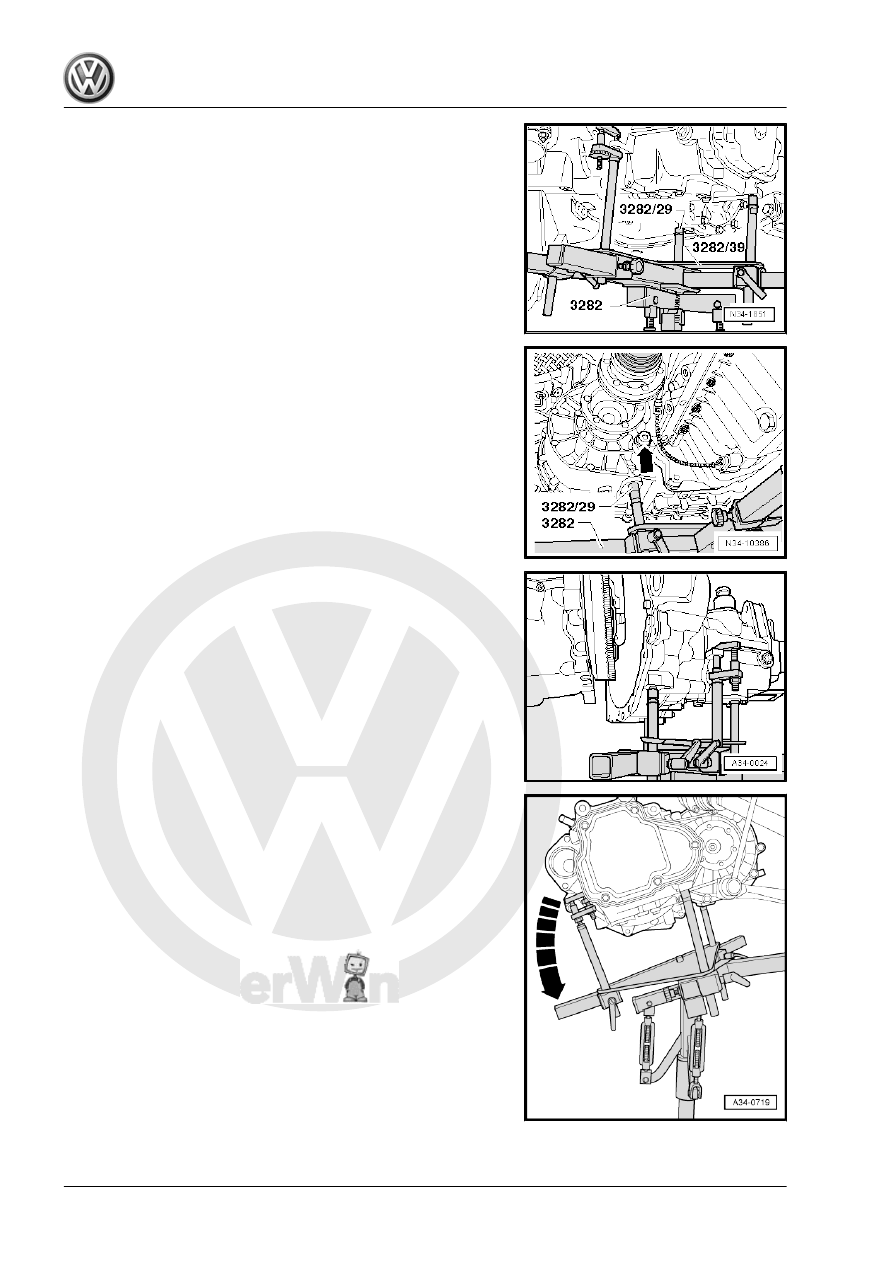
– Align the Adjusting Plate so that it is parallel to the transmis‐

sion and secure the safety support to the transmission.

– Install the Transmission Support - Pins 29 - 3282/29- into the

rear hole for the pendulum support bolt on the transmission.

– Remove the engine/transmission bolt near the right flange

-arrow-.

– Remove the lower engine/transmission bolts.

– Remove the transmission from the alignment bushings and

carefully move it toward the subframe.

– Tip the transmission over the adjusting spindle for the Trans‐

mission Support - 3282- in the direction of -arrow-.

– Carefully push the engine forward slightly with a second tech‐

nician.

– Carefully lower the transmission with the Engine and Gearbox

Jack - VAS6931- , while making sure that the right flange shaft

seal -1- is guided through without any damage to the pressure

plate -arrow-.

– Guide the left flange shaft -B- past the subframe -arrow- as

shown. Move the Engine and Gearbox Jack with the trans‐

mission to the front.

– When lowering, change position of transmission with spindles

on Transmission Support - 3282- .

– Reinsert the right flange shaft if necessary and tighten the bolt

-arrow- to the tightening specification.

Note

Pay attention to the lines when lowering the transmission.

Transmission, transporting. Refer to

⇒ “4 Transmission, Transporting”, page 89

 .

Tightening Specification
♦ Flange shaft to transmission. Refer to

⇒ “2.1 Overview - Differential”, page 189

 .

2.2

Transmission, Installing

Caution

This procedure contains mandatory replaceable parts. Refer

to component overview prior to starting procedure.

Mandatory Replacement Parts
♦ Bolt - Transmission Support to Transmission
♦ Bolt - Transmission Support to Transmission Bracket
♦ Bolt - Pendulum Support to Transmission
♦ Bolt - Pendulum Support to Subframe
♦ Bolts - Transmission Bracket to Transmission
♦ Bolts - Transmission Mount to Transmission Bracket
♦ Lock Washer - Cable Retainer

♦ Lock Washer - Gearshift Cable
♦ Nut - Coupling Rod to Stabilizer Bar
♦ Bolts - CV Boot to Inner CV Joint
♦ Seals - Transmission

Note

Refer to “Transmission, Removing” to get a list of the special tools

needed. Refer to 

⇒ “2.1 Transmission, Removing”, page 67

 .

Pay attention to the following list for the subject -“Transmission

Fluid, Checking and Filling”:

“Transmission Fluid, Checking and Filling”


»No«

»Yes«

»Yes«

Transmis‐

sion

Original

Part

X


No oil outlet

X


Was com‐

pletely dis‐

assembled

X

before in‐

stallation

-item 3-

⇒ Item 3

(page 119)

transmis‐

sion fluid

capacity.

Refer to

⇒ “4.2 Ca‐

pacities”,

page 6

 .


Was parti‐

ally disas‐

sembled

• (the

trans‐

mission

housing

and the

clutch

housing

were not

separa‐

ted from

each

other)


X

after instal‐

lation. Re‐

fer to

⇒ “8 Trans‐

mission

Fluid”, page

125

 .

– Use a thread cutter to carefully clean all threaded holes con‐

taining self-locking bolts to remove any locking compound

residue.

– Replace self-locking screws and nuts after removing them.
– Make sure the alignment sleeves for centering the engine/

transmission are installed inside the cylinder block. Install

them if necessary.

If the alignment sleeves are missing, it will be difficult to shift, there

will be clutch problems and the transmission may make noises

(loose rattling).
– Make sure the intermediate plate fits correctly on the engine.

– Clean the drive axle splines and grease lightly with Grease For

Clutch Disc Shaft Splines - G 000 100- .

It must be possible to slide the clutch plate back and forth on the

input shaft.
– Check clutch release bearing for wear, replace if necessary.
Align the Transmission Support - 3282- with the Transmission

Support - Mounting Plate 39 - 3282/39- in order to install the “0A4”

transmission.
– Align the arms of the Transmission Support so that they match

up with the holes in the Adjustment Plate .

– Install the Mounting Elements -A and C- ( Transmission Sup‐

port - Pins 29 - 3282/29- ) on the Adjusting Plate as illustrated.

– Place the transmission on the Engine and Gearbox Jack -

VAS6931- .

– Align the Adjustment Plate so that it is parallel to the trans‐

mission.

– Install the Transmission Support - Mounting Plate 29 -

3282/29- into the rear hole in the transmission for the pendu‐

lum support bolt.

– Position the Engine and Gearbox Jack under the vehicle. The

-arrow symbol B- on the adjusting plate points in direction of

travel.

– Remove from a new transmission or replacement transmis‐

sion right flange shaft -arrow-.

Note

Check the seal for leaks before removing the flange shaft. If

the seal has leaks, replace it when installing. Refer to

⇒ “1.3 Right Seal, Replacing”, page 185

 .

If transmission fluid leaks out while removing the flange shaft,

drain and refill transmission fluid on the installed transmission

and installed flange shaft. Refer to

⇒ “8 Transmission Fluid”, page 125

 .

– Attach the spindle -A- for the Seal Installer - Driver Set - 3066-

into the threaded piece on the differential.

– Insert the Seal Installer - One-Piece Seal - T10148- and se‐

cure with the nut -B-.

Note

The Seal Installer - One-Piece Seal - T10148- protects the

right seal and the transmission from dirt.

An M8 x 105 mm bolt may be installed by hand into the differ‐

ential threaded piece instead of a spindle -A-.


Content   ..  575  576  577  578   ..