Volkswagen Golf / Golf GTI / Golf Variant. Manual - part 575


  Index      Volkswagen     Volkswagen Golf / Golf GTI / Golf Variant - service repair manual 2013 year


Search            copyright infringement  


Content   ..  573  574  575  576   ..


Volkswagen Golf / Golf GTI / Golf Variant. Manual - part 575


♦ Bolt - Pendulum Support to Subframe
♦ Bolts - Transmission Bracket to Transmission
♦ Bolts - Transmission Mount to Transmission Bracket
♦ Lock Washer - Cable Retainer
♦ Lock Washer - Gearshift Cable
♦ Nut - Coupling Rod to Stabilizer Bar
♦ Bolts - CV Boot to Inner CV Joint
♦ Seals - Transmission
– Disconnect the battery ground cable. Refer to ⇒  Electrical

Equipment; Rep. Gr.  27 ; Battery; Battery, Disconnecting and

Connecting .

– Remove the engine cover. Refer to ⇒  Rep. Gr.  10 ; Engine

Cover; Engine Cover, Removing and Installing .

– Remove the air filter housing. Refer to ⇒  Engine Mechanical,

Fuel Injection and Ignition; Rep. Gr.  24 ; Air Filter; Air Filter

Housing, Removing and Installing .

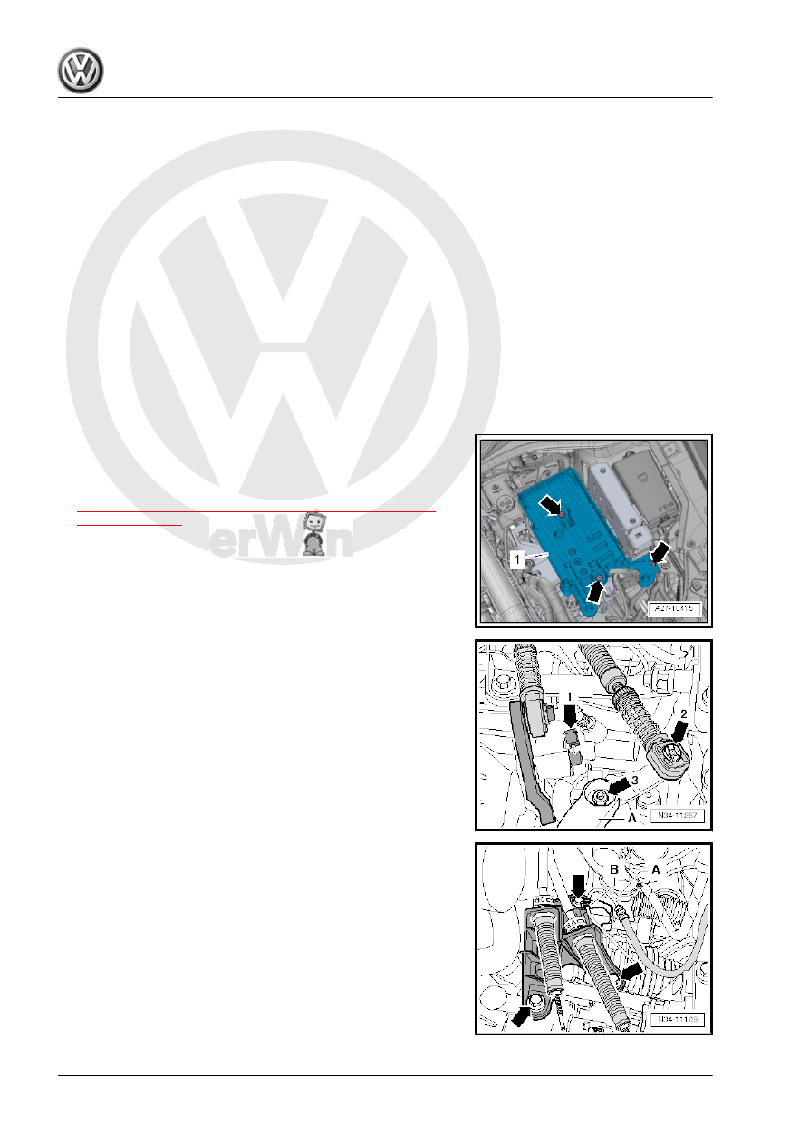
– Remove the battery and the battery tray -1- -arrows-. Refer to

⇒  Electrical Equipment; Rep. Gr.  27 ; Battery; Battery Tray,

Removing and Installing .

– Remove the cable retainer from the selector cable. Refer to

⇒ Fig. ““Disconnecting the Cable Retainer from the Selector

Cable”“ , page 57

 .

– Remove the clip -arrow 1- and then remove the relay lever and

the cable retainer.

– Remove the shift cable lock washer -arrow 2- from the selector

lever -A-.

– Remove the shift cable from the gearshift lever pins.
– Remove the nut -arrow 3- and then remove the transmission

shift lever -A-.

– Remove the cable mounting bracket from the transmission

-arrows-.

– Tie up the shift cable and the selector cable.
– If equipped, remove the bracket -B- from the transmission.

Remove the bracket from the hose/line assembly -A-.

– Remove the transmission support -A arrows-.
– Remove the clutch slave cylinder -B arrows- lay aside and se‐

cure with wire. Do not open the line system.

Caution

The clutch slave cylinder could be damaged.

♦ If the clutch slave cylinder is removed from the transmis‐

sion with pipe/hose line still connected, do not press the

clutch pedal.

– Remove the ground cable upward from the engine/transmis‐

sion connecting bolt or from the upper starter bolt.

– Disconnect the connector -arrow 1- from the Back-Up Lamp

Switch - F4- .

– Remove the connector -arrow 2- and wire -arrow 3- from the

starter.

– Remove the upper bolt from the starter.
– Remove the upper engine/transmission bolts.

– Unlock the retaining tab in direction of -arrow- and remove the

left engine cover mount -1-.

– Unclip the right mount -1- for the engine cover from the bracket

-2-.

– Attach the Engine Support Bridge - 10-222A- as follows:
The following are needed:
♦ Engine Support Bridge - Engine Support 18 - 10-222A/18-
♦ Engine Support - Bracket w/Spindle and hook - 10-222A/20-
♦ Engine/Gearbox Support Shackle (2 pc.) - 10-222A/12- (is

needed if the Spindle from the Engine Support Bridge cannot

be engaged in the engine lifting eye).

♦ Engine Support Bridge - Engine Support 29 - 10-222A/29-

(quantity 2)

♦ Engine Support - Basic Set Square Pipe - T40091/1- (quantity

2)

♦ Engine Support - Basic Set Movable Joint - T40091/3- (quan‐

tity 2)

♦ Engine Support - Supplement Kit Spindle - T40093/3- (quan‐

tity 2)

♦ Engine Support Brackets - T40093/3-6- (quantity 2)

– Insert the Engine Support Bridge - Engine Support 29 -

10-222A/29- between the fender bolting edge and the fender

bolting plate underneath it on both sides of the vehicle.

♦ Installed position:
“L” = -1- Adapter is Installed on the “right” Side of the Vehicle

( Adapter Locks in the Hole on the Fender).

“R” (Not Illustrated Here), Adapter is Installed on the “left” Side of

the Vehicle.
The arrow -2- on the Engine Support Bridge - Engine Support 29

- 10-222A/29- always points in the direction of travel.

– Slide the Engine Support Bridge - Engine Support 18 -

10-222A/18- and two Engine Support - Basic Set Movable

Joint - T40091/3- onto the Engine Support Bridge - 10-222A- .

– Tighten the Engine Support Bridge - 10-222A- on the Engine

Support Bridge - Engine Support 29 - 10-222A/29- .

-A- = Engine Support Brackets - T40093/3-6- (⇒ next illustration)
– Remove the filler tube for the windshield washer system wash‐

er fluid reservoir. Refer to ⇒  Electrical Equipment; Rep. Gr. 

92 ; Windshield Washer System; Washer Fluid Reservoir, Re‐

moving and Installing .

– If present, remove wires from the front area of both longitudinal

members -arrow-. Do not disconnect line system.

– Place the Engine Support Brackets - T40093/3-6- on both lon‐

gitudinal members (the right longitudinal member is illustrated

here).

– If necessary, carefully unclip the A/C system pipe in the front

area. Do not disconnect the line system. Refer to ⇒  Heating,

Ventilation and Air Conditioning; Rep. Gr.  87 ; Refrigerant

Circuit; System Overview - Refrigerant Circuit .

• The Engine Support Brackets - T40093/3-6- locks respectively

with the pins -A- behind the tab on the longitudinal member

-arrow-.

– Install the Engine Support - Supplement Kit Spindle -

T40093/3- .

– Connect the Engine Support - Supplement Kit Spindle -

T40093/3- over the Engine Support - Basic Set Square Pipe -

T40091/1- with the Engine Support Bridge - 10-222A- and

tension it (⇒ previous illustration).

Note

The Engine Support - Basic Set - Square Pipe - T40091/1-

must not touch the windshield.

The Engine Support Bridge - Engine Support 18 - 10-222A/18-

must not lie on the windshield wiper arm.

– Engage the Spindles with the Engine Support Bridge - Special

Hook (2 pc.) - 10-222A/20- and if necessary with the Engine/

Gearbox Support Shackle (2 pc.) - 10-222A/12- in the engine

lifting eyes.

– Pretension the engine/transmission assembly and Engine

Support Bridge via the Spindles .

– Raise the vehicle and remove the left front wheel.
– Remove the noise insulation. Refer to ⇒  Body Exterior; Rep.

Gr.  66 ; Noise Insulation; Overview - Noise Insulation .

– Remove the lower section of the left front wheel housing liner.

Refer to ⇒  Body Exterior; Rep. Gr.  66 ; Wheel Housing Liner;

Front Wheel Housing Liner, Removing and Installing .

– Remove the nut -arrow- and then remove the wire mount.


Content   ..  573  574  575  576   ..