Volkswagen Golf / Golf GTI / Golf Variant. Manual - part 573


  Index      Volkswagen     Volkswagen Golf / Golf GTI / Golf Variant - service repair manual 2013 year


Search            copyright infringement  


Content   ..  571  572  573  574   ..


Volkswagen Golf / Golf GTI / Golf Variant. Manual - part 573


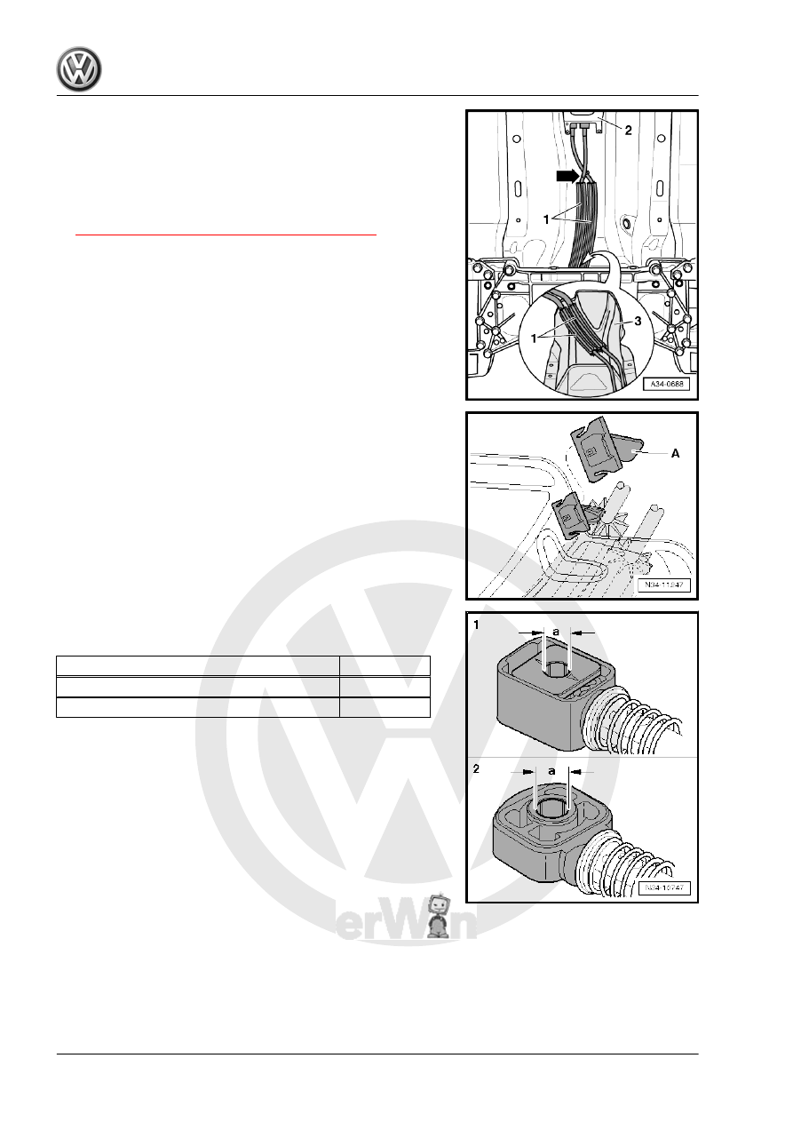
– Route the cables -1- from the gearshift mechanism -2- to the

transmission as follows:

♦ After the cables cross each other diagonally -arrow-, they must

run parallel to each other up to the cable mounting bracket on

the transmission.

♦ The cable tie -arrow- for securing the cables must be installed

correctly. Installation location. Refer to

⇒ Fig. ““Cable Tie Installation Locations”“ , page 59

 .

♦ The cables must be routed inside the depression in the heat

shield -3-.

A clip -A- holds the cables and heat shield to each other in place.

Cable Retainer Allocation
These holes have different diameters.

Cable Retainer For:

Dimension “a”

1. - Shift cable to transmission selector lever

8.5 mm

2. - selector cable to relay lever

10 mm

Selector Lever/Relay Lever Installed Position
1 - Gearshift lever
2 - The relay lever fits into the sliding rail on the transmission se‐

lector lever via the sliding shoe -arrow-.

• Lubricate the following areas very carefully when installing.
• Relay lever shaft -A- -arrows-.
• Gearshift lever glide track -B-, fits into the relay lever.
• Cable retainer locating bore.
• Grease allocation. Refer to the Parts Catalog.
• The selector relay lever and gearshift lever in the illustration

may differ from the Original Part.

Installing the Transmission Shift Lever
– When positioning the transmission shift lever, make sure the

tooth gap -arrow A- is placed over the missing selector shaft

teeth -arrow B-.

– Secure the shift cable with new lock washers to the gearshift

lever.

Install the Relay Lever and the Cable Retainer Together.

Note

Lubricate the bearing areas and the sliding surfaces. Grease al‐

location. Refer to the Parts Catalog.

– Install the relay lever and cable retainer -arrow 2- all the way

into the gearshift cover.

– Install the clip -arrow 1- and make sure it is locked into place.
– Install the selector cable in the cable retainer.
– Install the center console. Refer to ⇒  Body Interior; Rep. Gr. 

68 ; Center Console; Center Console, Removing and Instal‐

ling .

– Install the boot with the shifter knob and noise insulation. Refer

to 

⇒ “1.4 Gearshift Knob, Removing and Installing”, page 54

 .

– Install the heat shield under the gearshift mechanism. Refer

to ⇒  Body Exterior; Rep. Gr.  66 ; Molding/Trim/Extensions/

Trim Panels; Floor Heat Shield, Removing and Installing .

– Assemble the exhaust system free of tension. Refer to ⇒  Rep.

Gr.  26 ; Exhaust Pipes/Mufflers; Overview - Muffler .

– Adjust the gearshift mechanism. Refer to

⇒ “1.6 Selector Mechanism, Adjusting”, page 63

 .

– Install the air filter housing if it was removed earlier. Refer to

⇒  Engine Mechanical, Fuel Injection and Ignition; Rep. Gr. 

24 ; Air Filter; Air Filter Housing, Removing and Installing or ⇒ 

Engine Mechanical, Fuel Injection and Glow Plug; Rep. Gr. 

23 ; Air Filter; Overview - Air Filter Housing .

– Connect the battery. Refer to ⇒  Electrical Equipment; Rep.

Gr.  27 ; Battery; Battery, Disconnecting and Connecting .

Tightening Specifications
♦ Refer to

⇒ “1.2 Overview - Gearshift Knob and Cover”, page 52

♦ Refer to 

⇒ “1.3 Overview - Selector Mechanism”, page 53

 .

1.6

Selector Mechanism, Adjusting

Special tools and workshop equipment required
♦ Connecting Pin - T10027A-
Adjusting Requirements
• Operating and transfer elements of shift mechanism must be

in proper condition.

• Shift mechanism must move freely.
• The transmission, clutch and clutch mechanism must also be

in proper condition.

• Transmission in neutral.
– Remove the entire air filter housing if the bracket -A- and the

securing mechanism for the shift and selector cables are not

accessible. Refer to ⇒  Engine Mechanical, Fuel Injection and

Ignition; Rep. Gr.  24 ; Air Filter; Air Filter Housing, Removing

and Installing .

– Pull the safety mechanism on the cable retainer for the shift

cable and the selector cable all the way forward in direction of

-arrow 1- and then lock it to the left in direction of -arrow 2-.

Secure the gearshift shaft as follows:
– Push the gearshift shaft down in the direction of -arrow 1-.
– While press the gearshift shaft down, rotate the bracket -A- in

direction of -arrow 2- upward and simultaneously press it in

until it engages in the gearshift shaft.


Content   ..  571  572  573  574   ..