Volkswagen Golf / Golf GTI / Golf Variant. Manual - part 529
♦ Slide Hammer - Press Plate - 2050-
♦ Torque Wrench 1331 5-50Nm - VAG1331-
♦ Puller - Kukko Internal - 46-56mm - 21/07-
♦ Puller - Kukko Counterstay - 22/2-
♦ Dial Indicator - VAS6080A-
(Selecting the correct adjusting shim for the output shaft)
It is necessary to adjust the output shaft if the following compo‐
nents were replaced:
♦ Transmission Housing
♦ Clutch Housing
♦ Output shaft, 1st to 4th gears or
♦ Output shaft tapered roller bearing
Adjustment overview. Refer to
⇒ “3 Adjustment Overview”, page 221
Requirements:
• Remove any sealant still on the sealing surfaces on the clutch
and transmission housings.
• Install the output shaft that is going to be measured.
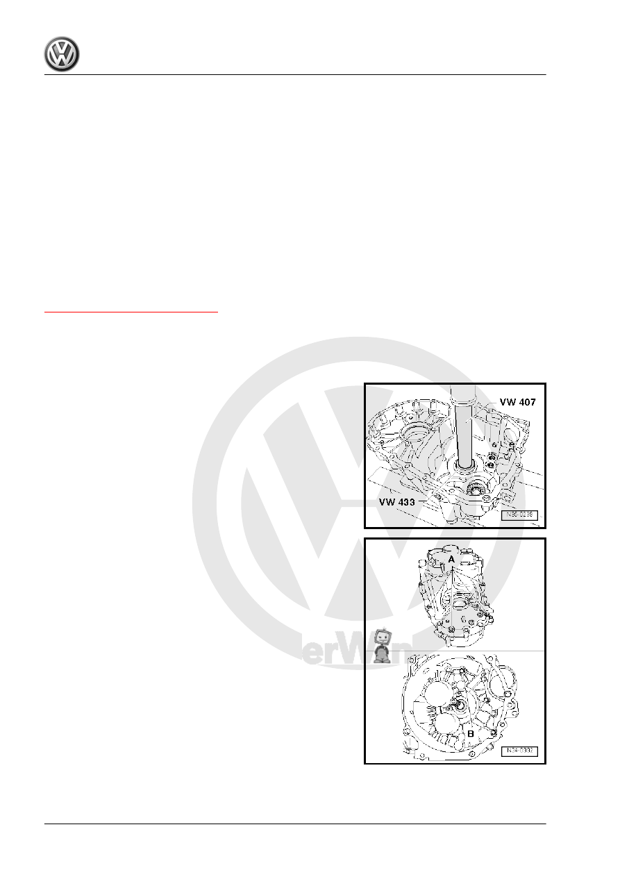
– Install the tapered roller bearing outer race in the transmission
housing with a 1.70 mm shim. Support transmission housing
directly beneath bearing mount using -2050- .
– Install the output shaft for 1st through 4th gears into the clutch
housing.
– Install the transmission housing and tighten the bolts
-A and B- diagonally.