Volkswagen Golf / Golf GTI / Golf Variant. Manual - part 528


  Index      Volkswagen     Volkswagen Golf / Golf GTI / Golf Variant - service repair manual 2013 year


Search            copyright infringement  


Content   ..  526  527  528  529   ..


Volkswagen Golf / Golf GTI / Golf Variant. Manual - part 528


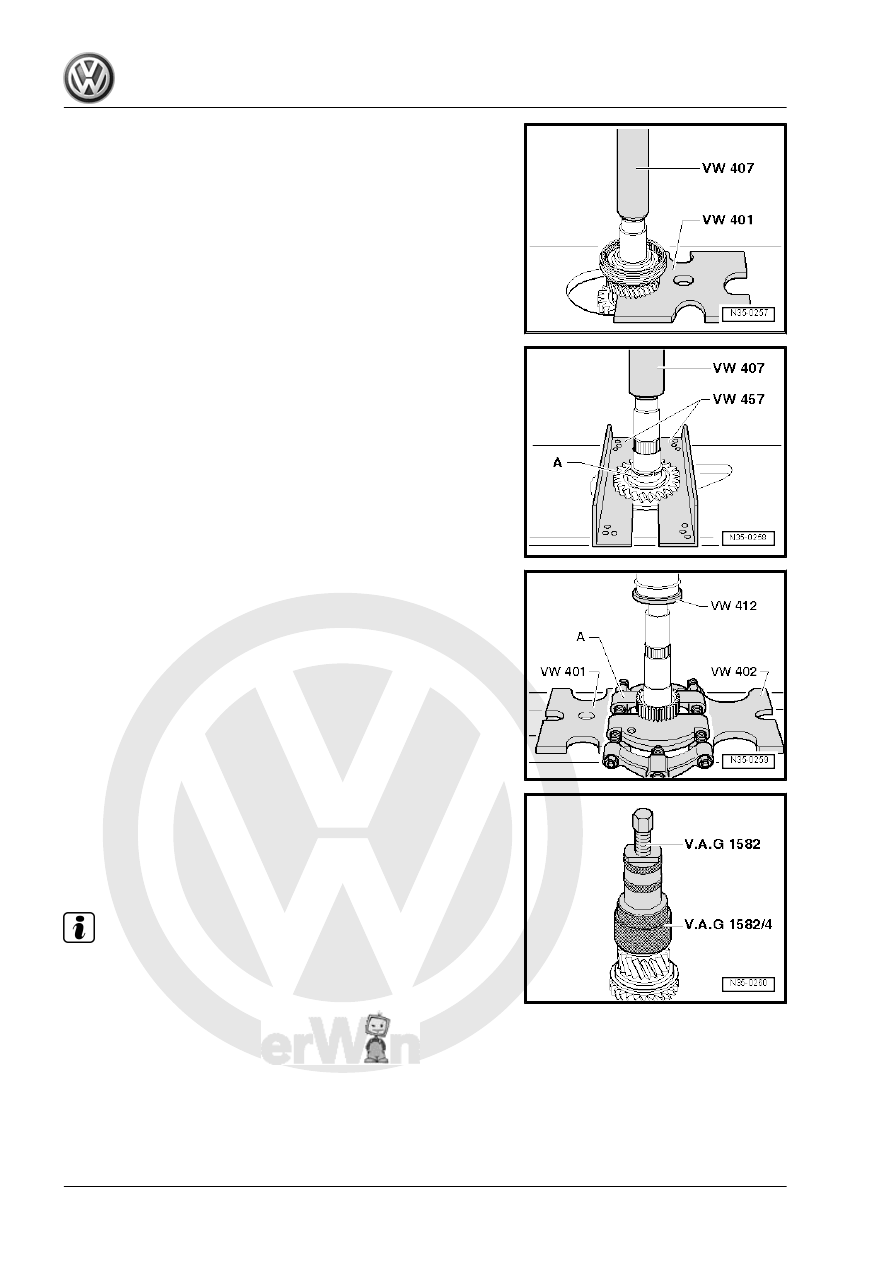
Removing the 5th and 6th Gear Synchronizer Hub/Locking Collar

with the 6th Gear Wheel
– Remove the locking ring beforehand.

Removing the Sleeve -A- together with the Reverse Gear Wheel
– Remove the locking ring beforehand.

Removing the Reverse Gear Synchronizer Hub
– Remove the locking ring beforehand.
A - Separating Tool 22-115mm , for example, -17/2-

Removing the Inner Race/Tapered Roller Bearing on the Side of

the Clutch Housing.
– Mount the -30-11- on the output shaft before removing the

puller.

Assemble the Output Shaft

Note

Heat the inner races of the tapered roller bearing and synchron‐

izer hub to approximately 100 °C (212 °F) with the -VAS6414-

before installing. Press on as far as the stop so there is no axial

play.

Installed Position: Reverse Gear Synchronizer Hub
• The stop -arrow A- on the reverse gear locking collar faces the

splines on the output shaft -arrow B-.

Warming and Installing the Reverse Gear Synchronizer Hub
– Install the locking ring.
– Mount the reverse gear locking collar on the reverse gear syn‐

chronizer hub.

– Install the reverse gear wheel and the needle bearing.

Installing the Sleeve -A-
• Installed position: wide collar points toward reverse gear se‐

lector gear.

– Install the locking ring.

Checking 5th and 6th Gear Synchronizer Ring for Wear

-A- = Brass Synchronizer Ring

Gap Dimension

-a-

Installation Dimen‐

sion

Wear Limit

5th and 6th gear

1.0 to 1.7 mm

0.5 mm

-B- = Steel Synchronizer Ring

Gap Dimension

-a-

Installation Dimen‐

sion

Wear Limit

5th and 6th gear

1.2 to 2.1 mm

0.8 mm

– Press synchronizer ring onto taper of the gear wheel and

measure gap dimension -a- using a feeler gauge.

Disassembling and Assembling Locking Collar and Synchronizer

Hub for 5th and 6th Gears
To disassemble, remove the springs -1-.
1 - Spring
2 - Locking piece
3 - Locking collar
4 - Synchronizer hub
– Slide the locking collar over the synchronizer hub.
• Installed position: The narrow locking piece recesses in the

synchronizer hub align with the recesses in the locking collar.

Assembling Locking Collar/Synchronizer Hub for 5th and 6th

Gears
• The locking collar is pushed over the synchronizer hub.
– Install the locking pieces and springs offset by 120°.
• The angled end of the spring must engage into the hollow

locking piece.

– Install the 6th gear wheel with needle bearing.
– Install the 6th gear synchronizer ring.

Installing the Locking Collar/Synchronizer Hub for 5th and 6th

Gears
On some locking collars, there is a chamfer on the outer diameter.
Installed position: The chamfer on the outer diameter of the lock‐

ing collar faces toward the 5th gear selector gear
– Turn the synchronizer ring so that the grooves line up with the

locking pieces.

– Install the locking ring.
– Install the 5th gear synchronizer ring.
– Install 5th gear wheel with needle bearing.

Installing the Inner Race/Tapered Roller Bearing on the side of

the Transmission Housing
– Choose the correct locking ring. Refer to

⇒ Fig. ““Selecting the Locking Ring”“ , page 187

 and install.

Selecting the Locking Ring
– Choose and install the thickest locking ring that will fit.
– Select the locking ring according to the Table. For the correct

part number. Refer to the Parts Catalog.

Available Locking Rings

Thickness (mm)

1.79

1.89

1.98

1.83

1.92


1.86

1.95


Installing the Inner Race/Tapered Roller Bearing on the side of

the Clutch Housing

2.3

Output Shaft, Adjusting

⇒ “2.3.1 Output Shaft, Adjusting, 1st through 4th Gear”,

page 187
⇒ “2.3.2 Output Shaft, 5th, 6th and Reverse Gears, Adjusting”,

page 190

2.3.1

Output Shaft, Adjusting, 1st through 4th

Gear

Special tools and workshop equipment required
♦ Transmission Support - VW353-
♦ Dial Gauge Holder - VW387-
♦ Press Piece - Rod - VW407-
♦ Press Piece - Multiple Use - VW433-
♦ Seal Installer - Stator - VW792-
♦ Crankshaft Holding Fixture - VW801-
♦ Holding Plate - VW309A-


Content   ..  526  527  528  529   ..