Volkswagen Golf / Golf GTI / Golf Variant. Manual - part 525


  Index      Volkswagen     Volkswagen Golf / Golf GTI / Golf Variant - service repair manual 2013 year


Search            copyright infringement  


Content   ..  523  524  525  526   ..


Volkswagen Golf / Golf GTI / Golf Variant. Manual - part 525


2.2

Output Shaft, Disassembling and As‐

sembling

⇒ “2.2.1 Output Shaft, Disassembling and Assembling, 1st to 4th

Gears”, page 172
⇒ “2.2.2 Output Shaft, 5th, 6th and Reverse Gears, Disassem‐

bling and Assembling”, page 182

2.2.1

Output Shaft, Disassembling and As‐

sembling, 1st to 4th Gears

Special tools and workshop equipment required
♦ Press Plate - VW401-
♦ Press Plate - VW402-
♦ Press Piece - Rod - VW407-
♦ Press Piece - Rod - VW408A-
♦ Press Piece - Multiple Use - VW412-
♦ Press Piece - 60mm - VW415A-
♦ Holding Plate - VW309A-
♦ Holding Fixture - VW313-
♦ Transmission Support - VW353-
♦ Press Piece - Multiple Use - VW431-
♦ Press Piece - Multiple Use - VW433-
♦ Press Piece - Multiple Use - VW454-
♦ Press Piece - Multiple Use - VW512-
♦ Press Piece - 42mm - VW516-
♦ Press Piece - Multiple Use - VW519-
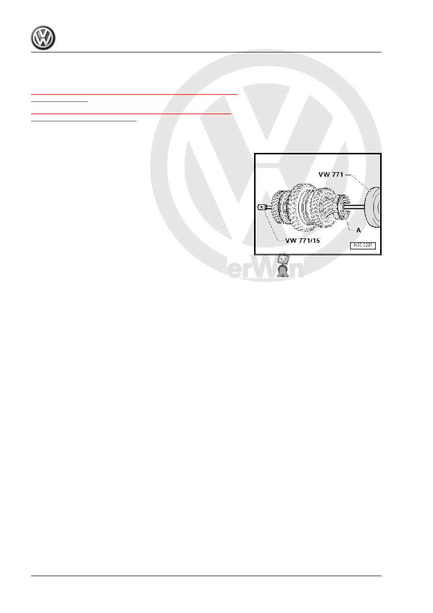
♦ Slide Hammer Set - VW771-
♦ Crankshaft Holding Fixture - VW801-
♦ Press Piece - Multiple Use - 40-105-
♦ Bearing Installer - Multiple Use - 40-20-
♦ Bearing Installer - Differential Bearing - 40-21-
♦ Press Piece - Multiple Use - 2050-
♦ Holding Fixture - Spacers - VW540/1B-
♦ Puller - Taper Roller Bearing - VAG1582-
♦ Puller - Taper Roller Bearing - Adapter 7 - VAG1582/7-
♦ Inductive Heater - VAS6414-
♦ Puller - Kukko Internal - 46-56mm - 21/7-
♦ Puller - Kukko Internal - 56-70mm - 21/8-
♦ Puller - Kukko Puller - 60-200mm Width, 250mm Length -

18/2-

♦ Puller - Kukko Quick Action Separating Tool - 22-115mm -

17/2-

♦ Puller - Kukko Counterstay - 22/2-
Removing the Dished Washer -A- from the Output Shaft

Installing the Dished Washer into the Output Shaft
Dimension “a” = 2 mm

Removing the Inner Race/Tapered Roller Bearing on the side of

the Clutch Housing
A - Separating Tool 22-115mm , for example, -17/2-

Installing the Inner Race/Tapered Roller Bearing on the Side of

the Clutch Housing

Removing the Outer Race / Tapered Roller Bearing from the

Clutch Housing
A - Counter Support , for example, -22/2-
B - Internal Puller 56 to 70 mm , for example, -21/8-

Installing the Outer Race/Tapered Roller Bearing in the Clutch

Housing
– Support the clutch housing with the -40-20- directly under the

bearing mount.

Remove the Inner Race/Tapered Roller Bearing on the side of the

Transmission Housing
Note the following before installing the -VAG1582- :
– Remove the inner race/tapered roller bearing locking ring on

the side facing the transmission housing.

– Place the -VW431- in the output shaft and lay the -40-105- on

top.

Installing the Inner Race/Tapered Roller Bearing on the side of

the Transmission Housing
– Choose the correct locking ring. Refer to

⇒ Fig. ““Selecting the Locking Ring”“ , page 174

 , and install.

Selecting the Locking Ring
– Choose and install the thickest locking ring that will fit.

Note

For the correct locking rings. Refer to the Parts Catalog.

The following circlips are available:

Thickness (mm)

1.79

1.83

1.86

1.89

1.92

1.95

1.98


Removing the Outer Race/Tapered Roller Bearing from the

Transmission Housing
A - Counter Support , for example, -22/2-
B - Internal Puller 46 to 58 mm , for example, -21/7-

Installing the Outer Race/Tapered Roller Bearing into the Trans‐

mission Housing
– Install the adjusting shim under the outer race.
– Support the transmission housing under the bearing mount

using the -2050- .

Disassembling the Output Shaft

Note

Remove the inner race/tapered roller bearing on the side of the

transmission housing. Refer to

⇒ Fig. ““Remove the Inner Race/Tapered Roller Bearing on the

side of the Transmission Housing”“ , page 174

 .

– Remove the locking ring.

Removing the 3rd and 4th Gear Synchronizer Hub/Locking Collar

with the 4th Gear Wheel
– Remove the locking ring beforehand.
– Then remove the retaining ring -Item 20-

⇒ Item 20 (page 165)

 and thrust washers -Item 19-

⇒ Item 19 (page 165)

 .

– Then remove the 1st gear wheel with synchronizer ring.

On Transmissions with Reinforcement Measures, Remove the

Collar Bushing -B- Together with the 1st Gear Wheel -C-.

Note

Allocate transmission via code letters:

A - Puller - Quick Action Separating Tool - 22-115mm , for exam‐

ple -Kukko 17/2-
– Install the Separating Tool -A- underneath the helical-cut gear

teeth on the 1st gear wheel.


Content   ..  523  524  525  526   ..