Volkswagen Golf / Golf GTI / Golf Variant. Manual - part 523
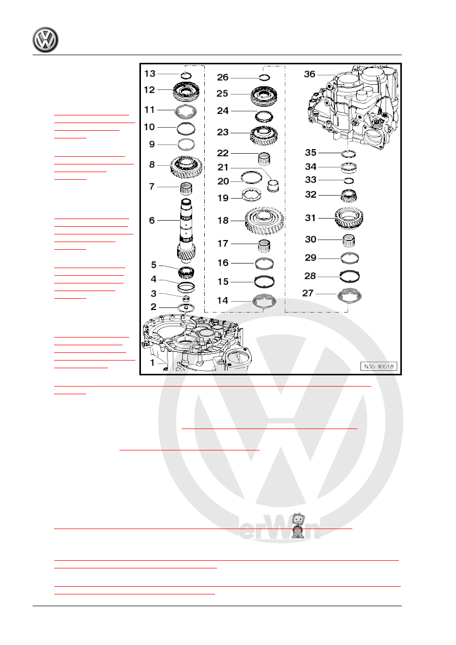
1 - Clutch Housing
2 - Oil Deflector Ring
3 - Dished Washer
❑ Removing. Refer to
❑ Installing. Refer to
4 - Outer Race/Tapered Roller
Bearing
❑ Removing. Refer to
❑ Installing. Refer to
5 - Inner Race / Tapered Roller
Bearing
❑ Removing. Refer to
❑ Installing. Refer to
⇒ Fig. ““Installing the Inner Race/Tapered Roller Bearing on the Side of the Clutch Housing”“ ,
6 - Output Shaft
❑ For 1st through 4th gear
❑ There are different versions. Refer to
⇒ Fig. ““Differentiation of Output Shafts”“ , page 168
❑ Allocate according to the transmission code letters. Refer to the Parts Catalog.
❑ Adjusting. Refer to
⇒ “2.3 Output Shaft, Adjusting”, page 187
7 - Needle Bearing
❑ For 2nd gear
8 - 2nd Gear Wheel
9 - 2nd Gear Inner Race
❑ Replace if there are wear grooves
❑ Installed position. Refer to
⇒ Fig. ““Installing 2nd Gear Outer Race, Inner Race and Synchronizer Ring”“ , page 177
10 - 2nd Gear Outer Race
❑ Check the inner friction surface for wear. Refer to
⇒ Fig. ““Checking the Inner Contact Surface for Wear on the 1st Gear Outer Ring, the 2nd Gear Outer
Ring, and the 3rd Gear Outer Ring ”“ , page 176
❑ Check the outer friction surface for wear. Refer to
⇒ Fig. ““Checking the Outer Contact Surface for Wear on the 1st Gear Outer Ring, the 2nd Gear Outer