Volkswagen Golf / Golf GTI / Golf Variant. Manual - part 511


  Index      Volkswagen     Volkswagen Golf / Golf GTI / Golf Variant - service repair manual 2013 year


Search            copyright infringement  


Content   ..  509  510  511  512   ..


Volkswagen Golf / Golf GTI / Golf Variant. Manual - part 511


5.6

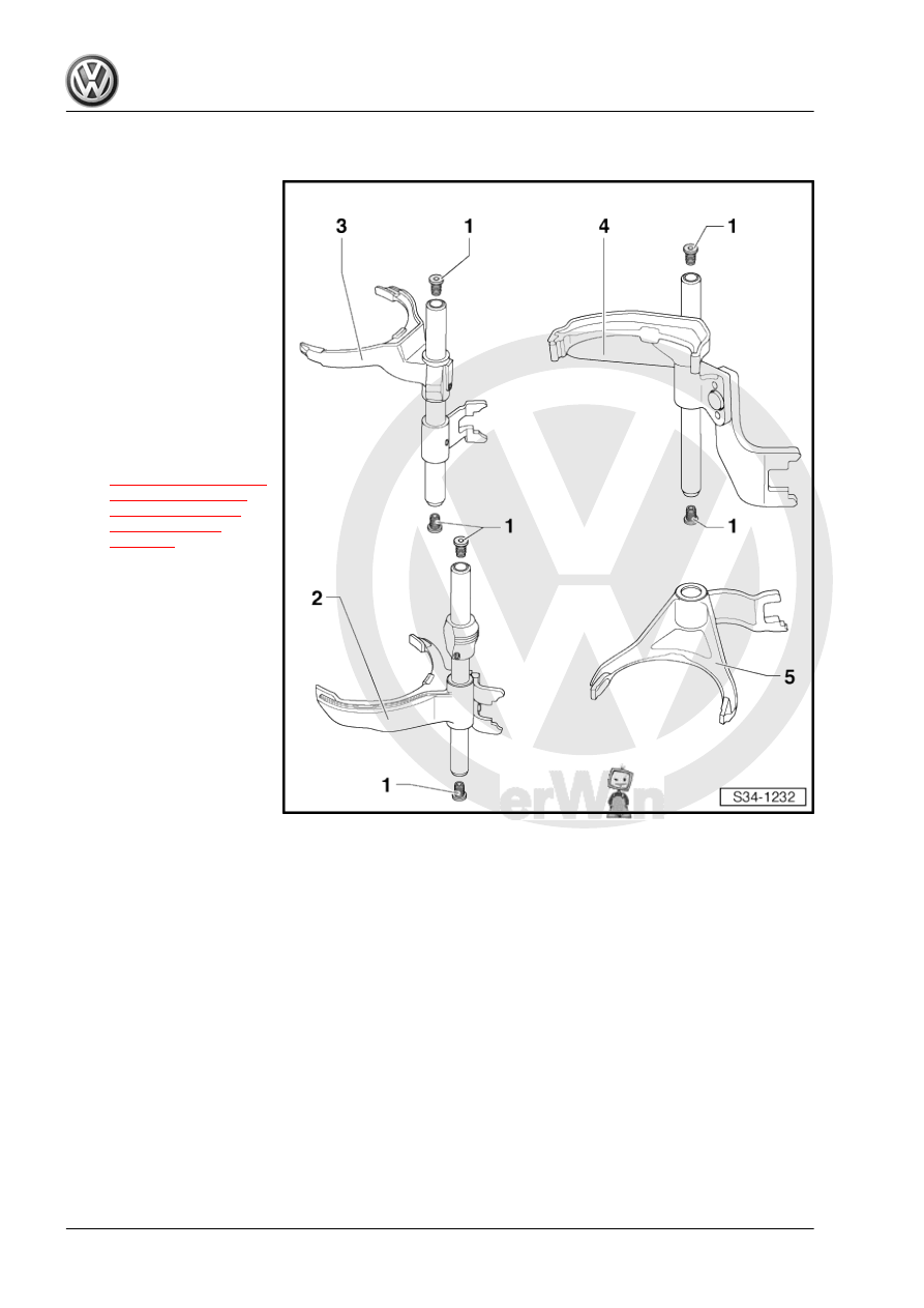
Overview - Shift Forks

1 - Insulation Mat

❑ Remove from the shift

lever rod by hand and

install.

2 - Shift Lever Rod with Shift

Fork for 1st Gear and 2nd Gear
3 - Shift Lever Rod with Shift

Fork for 3rd Gear and 4th Gear
4 - Shift Lever Rod with Shift

Fork for 5th Gear and 6th Gear
5 - Reverse Gear Shift Fork

❑ Is secured on the shift

lever rod with 5th and

6th gear shift fork. Refer

to

⇒ Fig. ““Installation Lo‐

cation of Shafts and

Shift Lever Rods in

Transmission”“ ,

page 115

5.7

Transmission, Disassembling and As‐

sembling

Special tools and workshop equipment required
♦ Holding Plate - VW309A-
♦ or Holding Plate - VW309A-
♦ Holding Fixture - VW313-
♦ Transmission Support - VW353-
♦ Press Piece - Multiple Use - VW455- or Press Piece - Front

Wishbone - 3160-

♦ Slide Hammer Set - VW771-
♦ Puller - Kukko Internal - 12-16mm - 21/1-
♦ Puller - Kukko Quick Action Separating Tool - 5-60mm - 17/0-
♦ -4- Counter Support - VAS251621-
♦ Puller - Kukko Counterstay - 22/1-

♦ Bracket - Multiple Use - 30-211A-
♦ Seal Installer - Drive Flange - T10143- or Seal Installer - Out‐

put Shaft Oil Seal - T10180-

♦ Locking Sleeve Drift - T10169-
♦ or Locking Sleeve Drift - T10362- . Refer to

⇒ Fig. ““Lock Sleeve Differentiation”“ , page 136

♦ Seal Installer - Driveshaft - T40008-
♦ Torque Wrench 1331 5-50Nm - VAG1331-
♦ Hot Air Blower - VAG1416-
♦ Pry Lever - 80-200-
♦ Shop Crane - Drip Tray - VAS6208-
♦ Sealing Compound - AMV 188 200 03-

Caution

This procedure contains mandatory replaceable parts. Refer

to component overview prior to starting procedure.

Mandatory Replacement Parts
♦ Seal - Back-Up Lamp Switch
♦ Seal - Oil Drain Plug
♦ Locking Bolt - Transmission Housing
♦ Bolt - Transmission Housing
♦ Bolt - Shift Lever Unit
♦ O-ring - Shift Lever Unit
♦ Bolt - Clutch Slave Cylinder with Release Bearing
Transmission Housing, Shift Mechanism, Input Shaft, Output

Shafts, Differential and Gearshift Rods, Removing and Installing.
Disassemble Transmission
– Secure the transmission on the -VW353- -arrows-.

Note

If one of the fastening holes does not touch the -VW353- , place

washers between the fastening hole and the -VW353- .

– Turn the transmission the assembly stand with the oil drain

plug facing down.

– Place the -VAS6208- underneath.
– Drain the transmission fluid.

– Remove the right flange shaft (the illustration shows the left

flange shaft).

– Remove the flange shaft and the pressure spring.

– Remove the clutch slave cylinder with the release bearing

-arrows-.

– Transmission for vehicles with start/stop system: Remove the

Transmission Neutral Position Sensor - G701- -arrow-.

Make Sure the Shift Lever Shaft is Not Blocked By the Lock Elbow

-arrow-.
– Move the shift lever shaft into neutral.
– Remove the Back-Up Lamp Switch - F4- -1-.
– Remove the locking bolt -2-.
– Then remove the bolts -3-.
– Remove selector shaft with shift cover -4- from transmission

housing.

Note

Use the -80-200- to press against the spring force of the securing

bushing direction of -arrow- so that the shift lever shaft -1- does

not touch the securing bushing -2- when removing.

– Remove the left flange shaft bolt. To do this, install two bolts

in the flange and counterhold it using a pry bar.

– Remove the flange shaft and the pressure spring.

– Remove the bolts -B- that connect the clutch housing to the

transmission housing.

Note

One bolt -arrow- is located outside of the bolting flange.

– Lock the input shaft as follows:
The Stub Shaft Splines on the Input Shaft Has Different Lengths

on the Transmission.
– Either place the -VW455- over the input shaft on the clutch

housing.


Content   ..  509  510  511  512   ..