Volkswagen Golf / Golf GTI / Golf Variant. Manual - part 509


  Index      Volkswagen     Volkswagen Golf / Golf GTI / Golf Variant - service repair manual 2013 year


Search            copyright infringement  


Content   ..  507  508  509  510   ..


Volkswagen Golf / Golf GTI / Golf Variant. Manual - part 509


4

Transmission, Transporting

⇒ “4.1 Transmission, Transporting”, page 108

4.1

Transmission, Transporting

Special tools and workshop equipment required
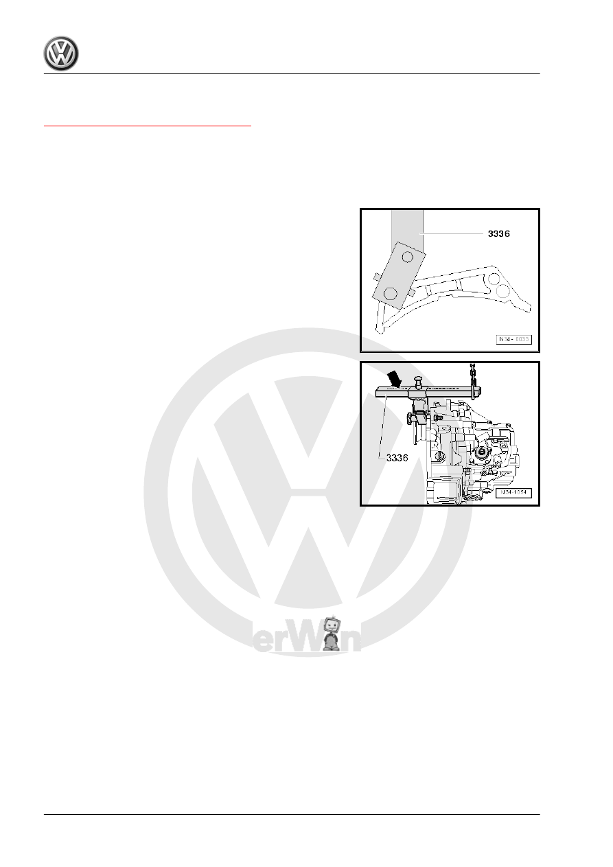
♦ Transmission Support Jig - 3336-
♦ Shop Crane - VAS6100-
– Attach the -3336- to the clutch housing.

– Move the support arm on the sliding bar using the locking bolt

-arrow-.
Number of visible holes are six.

– Lift the transmission using the -VAS6100- and the Transmis‐

sion Support Jig .

– Set the transmission down, for example, into the transport

container.

5

Transmission, Disassembling and

Assembling

⇒ “5.1 Overview - Schematic, Transmission”, page 109
⇒ “5.2 Overview - Transmission”, page 110
⇒ “5.3 Overview - Transmission Housing and Selector Mecha‐

nism”, page 111
⇒ “5.4 Overview - Shift Unit”, page 113
⇒ “5.5 Overview - Input Shaft, Output Shafts, Differential, Shift

Lever Rods”, page 114
⇒ “5.6 Overview - Shift Forks”, page 116
⇒ “5.7 Transmission, Disassembling and Assembling”,

page 116

5.1

Overview - Schematic, Transmission

1 - Clutch Housing
2 - Reverse Shaft
3 - Output Shaft, 5th/6th and

Reverse Gears
4 - Clutch Slave Cylinder with

Release Bearing
5 - Input Shaft
6 - Output Shaft, 1st to 4th

Gears
7 - Differential
8 - Right Flange Shaft
9 - Left Flange Shaft
10 - 2nd Gear Wheel
11 - 1st Gear Wheel
12 - 4th Gear Wheel
13 - 3rd Gear Wheel
14 - 5th Gear Wheel
15 - 6th Gear Wheel
16 - Reverse Gear Wheel
17 - Transmission Housing

5.3

Overview - Transmission Housing and Selector Mechanism

1 - Bolt

❑ Removing and instal‐

ling. Refer to

⇒ “2.1 Overview - Differ‐

ential”, page 212

 .

2 - Left Flange Shaft

❑ With pressure spring

and tapered ring

❑ Removing and instal‐

ling. Refer to

⇒ “1.2 Left Seal, Replac‐

ing”, page 207

 .

❑ Assembling. Refer to

⇒ “2.1 Overview - Differ‐

ential”, page 212

 .

3 - Locking Ring

❑ For the metal cover
❑ Not used in plastic cov‐

ers

4 - Cover

❑ Secured with metal

locking ring

❑ Without plastic locking

ring

❑ Allocate the compo‐

nents using the Parts

Catalog.

❑ Made of metal or plastic.

Refer to 

⇒ page 120

5 - Locking Ring

❑ For the grooved ball

bearing/input shaft. Re‐

fer to

⇒ “1.1 Overview - Input

Shaft”, page 157

 .

❑ The thickness must be determined again on transmissions with reinforcements (manual transmission

0FB). Refer to 

⇒ page 125

 .

6 - Back-Up Lamp Switch - F4-

❑ 20 Nm
❑ With permanent seal

7 - Seal

❑ If present, replace after removing
❑ Not installed on all transmissions

8 - Oil Drain Plug

❑ Tightening specification. Refer to 

⇒ Fig. ““Different Versions of Fluid Fill and Drain Plugs”“ , page 142

9 - Seal

❑ Replace after removing

10 - Bolt

❑ 6 Nm

11 - Transmission Neutral Position Sensor - G701-

❑ For vehicles with the Start/Stop System


Content   ..  507  508  509  510   ..