Volkswagen Golf / Golf GTI / Golf Variant. Manual - part 508


  Index      Volkswagen     Volkswagen Golf / Golf GTI / Golf Variant - service repair manual 2013 year


Search            copyright infringement  


Content   ..  506  507  508  509   ..


Volkswagen Golf / Golf GTI / Golf Variant. Manual - part 508


– Connect the connector -1- to the Oil Level Thermal Sensor -

G266- .

– Gear oil level in manual transmission, checking. Refer to

⇒ “8.1 Transmission Fluid Level, Checking”, page 142

 .

– If unclipped, carefully clip in the A/C system pipe and do not

disconnect the line system. Refer to ⇒  Heating, Ventilation

and Air Conditioning; Rep. Gr.  87 ; Refrigerant Circuit; System

Overview - Refrigerant Circuit .

– Install the battery tray, battery and the battery cover. Refer to

⇒  Electrical Equipment; Rep. Gr.  27 ; Battery; Battery Tray,

Removing and Installing .

– Install the air filter housing. Refer to ⇒  Engine Mechanical,

Fuel Injection and Ignition; Rep. Gr.  24 ; Air Filter; Air Filter

Housing, Removing and Installing .

– Install the engine cover. Refer to ⇒  Rep. Gr.  10 ; Engine

Cover; Engine Cover, Removing and Installing .

– Install the lower section of the left front wheel housing liner.

Refer to ⇒  Body Exterior; Rep. Gr.  66 ; Wheel Housing Liner;

Front Wheel Housing Liner, Removing and Installing .

– Install the noise insulation. Refer to ⇒  Body Exterior; Rep. Gr. 

66 ; Noise Insulation; Overview - Noise Insulation .
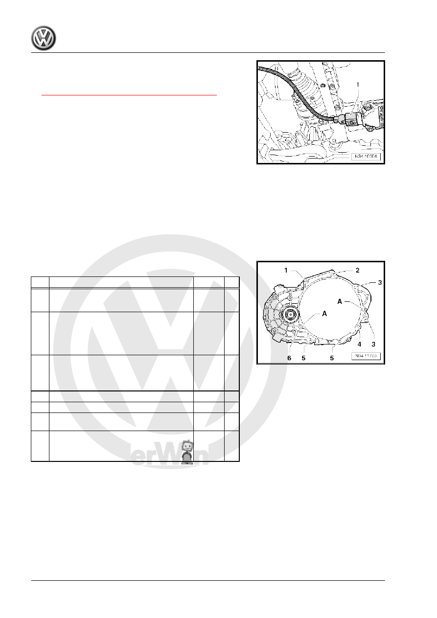
2.3

Transmission Tightening Specifications

Item

Bolt

Quantity Nm

1

M12 x 55

♦ With a long M8 threaded pin

1

80

2

M12 x 55

♦ With a short M8 threaded pin or

M12 x 50

♦ Without threaded pin

1

80

3

M12 x 165

♦ With an M8 threaded pin
♦ Also starter to transmission

2

80

4

M10 x 105

1

40

5

M10 x 50

2

40

6

M12 x 70

or M12 x 65

1

80

-

M6 x 8

♦ Small flywheel cover plate (not present

on all engines)

1

10

-A- Alignment sleeves for centering

3

Subframe Mount

⇒ “3.1 Overview - Subframe Mount”, page 105

3.1

Overview - Subframe Mount

1 - Bolt

❑ Ttightening specifica‐

tion. Refer to ⇒  Engine

Mechanical, Fuel Injec‐

tion and Ignition; Rep.

Gr.  10 ; Subframe

Mount; Overview - Sub‐

frame Mount .

2 - Engine Support

❑ Refer to ⇒  Engine Me‐

chanical, Fuel Injection

and Ignition; Rep. Gr. 

10 ; Subframe Mount;

Overview - Subframe

Mount .

3 - Engine Mount

❑ Refer to ⇒  Engine Me‐

chanical, Fuel Injection

and Ignition; Rep. Gr. 

10 ; Subframe Mount;

Overview - Subframe

Mount .

4 - Bolt

❑ Tightening specifica‐

tion. Refer to ⇒  Engine

Mechanical, Fuel Injec‐

tion and Ignition; Rep.

Gr.  10 ; Subframe

Mount; Overview - Sub‐

frame Mount .

5 - Bolt

❑ Tightening specifica‐

tion. Refer to ⇒  Engine

Mechanical, Fuel Injec‐

tion and Ignition; Rep.

Gr.  10 ; Subframe

Mount; Overview - Subframe Mount .

6 - Bolt

❑ Tightening specification. Refer to ⇒  Engine Mechanical, Fuel Injection and Ignition; Rep. Gr.  10 ; Sub‐

frame Mount; Overview - Subframe Mount .

7 - Bolt

❑ Tightening specification. Refer to ⇒  Engine Mechanical, Fuel Injection and Ignition; Rep. Gr.  10 ; Sub‐

frame Mount; Overview - Subframe Mount .

8 - Pendulum Support

❑ Refer to ⇒  Engine Mechanical, Fuel Injection and Ignition; Rep. Gr.  10 ; Subframe Mount; Overview -

Subframe Mount .

9 - Bolt

❑ For pendulum support to subframe
❑ Refer to ⇒  Engine Mechanical, Fuel Injection and Ignition; Rep. Gr.  10 ; Subframe Mount; Overview -

Subframe Mount .

10 - Bolt

❑ For pendulum support to transmission
❑ Refer to ⇒  Engine Mechanical, Fuel Injection and Ignition; Rep. Gr.  10 ; Subframe Mount; Overview -

Subframe Mount .

❑ Transmission with threaded insert. Refer to

⇒ Fig. ““Transmission with Threaded Insert (for example Heli Coil) for Attaching the Pendulum Support”“ ,

page 107

11 - Bolt

❑ For pendulum support to transmission
❑ Refer to ⇒  Engine Mechanical, Fuel Injection and Ignition; Rep. Gr.  10 ; Subframe Mount; Overview -

Subframe Mount .

❑ Transmission with threaded insert. Refer to

⇒ Fig. ““Transmission with Threaded Insert (for example Heli Coil) for Attaching the Pendulum Support”“ ,

page 107

12 - Bolt

❑ 60 Nm + 90°
❑ Replace after removing
❑ For transmission mount to transmission bracket
❑ Tightening sequence. Refer to

⇒ Fig. ““Attaching the Transmission Mount -2- to the Transmission Bracket -1- ”“ , page 107

 .

13 - Bolt

❑ 60 Nm + 90°
❑ Replace after removing
❑ For transmission mount to transmission bracket
❑ Tightening sequence. Refer to

⇒ Fig. ““Attaching the Transmission Mount -2- to the Transmission Bracket -1- ”“ , page 107

 .

14 - Transmission Mount

❑ Check the adjustment. Refer to ⇒  Engine Mechanical, Fuel Injection and Ignition; Rep. Gr.  10 ; Subframe

Mount; Subframe Mount, Checking Adjustment

❑ Adjusting. Refer to ⇒  Engine Mechanical, Fuel Injection and Ignition; Rep. Gr.  10 ; Subframe Mount;

Subframe Mount, Adjusting

15 - Bolt

❑ Transmission mount to chassis
❑ Refer to ⇒  Engine Mechanical, Fuel Injection and Ignition; Rep. Gr.  10 ; Subframe Mount; Subframe

Mount, Adjusting .

16 - Bolt

❑ 60 Nm +90°
❑ Replace after removing
❑ For transmission bracket to transmission
❑ Tightening sequence. Refer to 

⇒ Fig. ““Transmission Bracket -1- to Transmission.”“ , page 107

 .

17 - Transmission Bracket
18 - Bolt

❑ 60 Nm +90°
❑ Replace after removing
❑ For transmission bracket to transmission
❑ Tightening sequence. Refer to 

⇒ Fig. ““Transmission Bracket -1- to Transmission.”“ , page 107

 .

Transmission with Threaded Insert (for example “Heli Coil”) for

Attaching the Pendulum Support

Note

There are threaded inserts (for example “Heli Coil”) in the pen‐

dulum support fastening holes.

How to recognize: Shoulder on the first thread -arrow-.

Make sure to use the appropriate bolts and observe the tight‐

ening specification. Refer to ⇒  Engine Mechanical, Fuel In‐

jection and Ignition; Rep. Gr.  10 ; Subframe Mount; Overview

- Subframe Mount ..

Transmission Bracket -1- to Transmission.
– Replace the bolts -arrows-.
– Tighten the bolts -arrows- hand-tight.
– Tighten the bolts -arrows-.

Attaching the Transmission Mount -2- to the Transmission Brack‐

et -1-
– Replace the bolts -arrows-.
– Tighten the bolts -arrows- hand-tight.
– Tighten the bolts -arrows-.


Content   ..  506  507  508  509   ..