Volkswagen Golf / Golf GTI / Golf Variant. Manual - part 503
 

  Index      Volkswagen     Volkswagen Golf / Golf GTI / Golf Variant - service repair manual 2013 year


Search            copyright infringement  


Content   ..  501  502  503  504   ..


Volkswagen Golf / Golf GTI / Golf Variant. Manual - part 503


♦ Engine Sling - Engine Bracket - 2024A/1- from Engine Sling -

2024A-

♦ Grease for Clutch Plate Shaft Splines - G 000 100-
♦ Allocate the grease for gearshift mechanism. Refer to the

Parts Catalog.

♦ M10 x 20 hex bolt

Caution

This procedure contains mandatory replaceable parts. Refer

to component overview prior to starting procedure.

Mandatory Replacement Parts
♦ Nut - Selector Lever to Shift Lever Shaft with Shift Lever Cover
♦ Lock Washer - Cable Retainer to Selector Lever
♦ Lock Washer - Cable Mounting Bracket to Cable Retainer
♦ Bolt - Pendulum Support to Transmission
♦ Bolt - Transmission Bracket to Transmission
– Disconnect the battery ground cable. Refer to ⇒  Electrical

Equipment; Rep. Gr.  27 ; Battery; Battery, Disconnecting and

Connecting .

– Remove the engine cover. Refer to ⇒  Rep. Gr.  10 ; Engine

Cover; Engine Cover, Removing and Installing .

– Remove the air filter housing. Refer to ⇒  Engine Mechanical,

Fuel Injection and Ignition; Rep. Gr.  24 ; Air Filter; Air Filter

Housing, Removing and Installing .

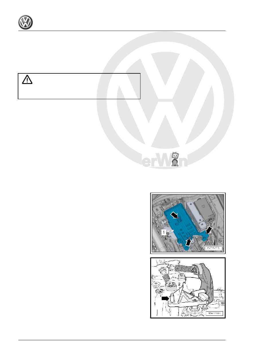
– Remove the battery and the battery tray -1- -arrows-. Refer to

⇒  Electrical Equipment; Rep. Gr.  27 ; Battery; Battery, Dis‐

connecting and Connecting .

– Remove the shift cable lock washer -1- from the transmission

selector lever -2-. Remove the cable from the pin -arrow-.

– Remove the cable retainer from the selector cable.
• To avoid damage to the selector cable, the cable retainer must

be disconnected from the selector lever before removal.

– Pull the safety mechanism all the way forward in the direction

of -arrow 1-. Then lock it to the left in the direction of

-arrow 2-.

– Push the relay lever forward (in the direction of -arrow 3-).

Note

Only remove the cable retainer when the relay lever is removed.

Refer to

⇒ Fig. ““With the Selector Relay Lever Removed: Pry the Selector

Cable Retainer Out of the Selector Relay Lever.”“ , page 67

 .

– Remove nut -1- and bolts -2- and set the cable bracket and

cables off to the side.

Note

Brake fluid must not come into contact with the longitudinal mem‐

ber or transmission. If it does, clean the area thoroughly.

– Unclamp the supply hose to the clutch master cylinder with a

-3094- .

Note

A slight deformation of the supply hose remains after the

-3094- has been unclamped.

The supply hose is therefore not defective.

After removing the -3094- , the supply hose must be formed

back into its original shape.

– Place a lint-free cloth under the bleeder.
– Remove the clip -arrow- all the way and then remove the hose/

line assembly -A- from the bleeder.

– Tie up wire.
The ground cable -B-, if present, is installed later in the procedure.
– Seal the open lines and connections with clean plugs from the

-VAS6122- .

Caution

There is a risk of contamination from the leaking brake fluid.

♦ Do not use the clutch pedal if the hose/line assembly from

the clutch slave cylinder bleeder is disconnected.

– Remove the upper engine/transmission connecting bolts

-arrows-.

– Disconnect any hoses and cables in the area of the -10-222A-

lifting eyes on the engine.

– Attach the -10-222A- as follows:
The following are needed:
♦ -10-222A/18-
♦ -10-222A/12- (is needed if the Spindle from the -10–222A-

cannot be engaged in the engine lifting eye).

♦ -10-222A/29- (quantity 2)
♦ -T40091/1- (quantity 2)
♦ -T40091/3- (quantity 2)
♦ -T40093/3- (quantity 2)
♦ -T40093/3-6- (quantity 2)
♦ -10-222A/20-

– Insert the -10-222A/29- between the fender bolting edge and

the fender bolting plate underneath it on both sides of the ve‐

hicle.

♦ Installed position:
“L” = -1- Adapter is inserted on the “right” side of the vehicle

( Adapter locks in place in the fender opening).
“R” (not illustrated here), Adapter is installed on the “left” side of

the vehicle.
The arrow -2- always points in driving direction

– Slide the -10-222A/18- and two -T40091/3- onto the

-10-222A- .

– Tighten the -10-222A- on the -10-222A/29- .
-A- is the -T40093/3-6- (refer to the next illustration)
– Remove the filler tube for the windshield washer system wash‐

er fluid reservoir. Refer to ⇒  Electrical Equipment; Rep. Gr. 

92 ; Windshield Washer System; Washer Fluid Reservoir, Re‐

moving and Installing .

– If present, remove wires from the front area of both longitudinal

members -arrow-. Do not disconnect line system.

– Place the -T40093/3-6- on both longitudinal members (the

right longitudinal member is illustrated here).

– If necessary, carefully unclip the A/C system pipe in the front

area. Do not disconnect the line system. Refer to ⇒  Heating,

Ventilation and Air Conditioning; Rep. Gr.  87 ; Refrigerant

Circuit; System Overview - Refrigerant Circuit .

• The -T40093/3-6- locks respectively with the pins -A- behind

the tab on the longitudinal member -arrow-.

– Install the -T40093/3- .
– Connect the -T40093/3- over the -T40091/1- with the

-10-222A- and tension it (⇒ previous illustration).

– Engage the -T40093/3- into the engine lifting eyes as illustra‐

ted in the previous illustration. If necessary, use -10-222A/12- .

– Pretension the engine/transmission assembly and -10–222A-

via the -T40093/3- .

– Disconnect the front left connectors from the transmission:
1 - Transmission for vehicles with start/stop system: Transmis‐

sion Neutral Position Sensor - G701-

2 - Back-Up Lamp Switch - F4-
– Remove the noise insulation. Refer to ⇒  Body Exterior; Rep.

Gr.  66 ; Noise Insulation; Overview - Noise Insulation .

– Remove the lower section of the left front wheel housing liner.

Refer to ⇒  Body Exterior; Rep. Gr.  66 ; Wheel Housing Liner;

Front Wheel Housing Liner, Removing and Installing .

– Remove the starter. Refer to ⇒  Electrical Equipment; Rep. Gr. 

27 ; Starter; Starter, Removing and Installing .

– Disconnect the connector -1- from the Oil Level Thermal Sen‐

sor - G266- .

– Remove the left charge air hose -1-. Refer to ⇒  Engine Me‐

chanical, Fuel Injection and Ignition; Rep. Gr.  21 ; Charge Air

System; Overview - Charge Air System .


Content   ..  501  502  503  504   ..