Volkswagen Golf / Golf GTI / Golf Variant. Manual - part 502


  Index      Volkswagen     Volkswagen Golf / Golf GTI / Golf Variant - service repair manual 2013 year


Search            copyright infringement  


Content   ..  500  501  502  503   ..


Volkswagen Golf / Golf GTI / Golf Variant. Manual - part 502


– Remove fuel filter and set off to the side. Do not open the line

system. Refer to ⇒  Fuel Supply System; Rep. Gr.  20 ; Fuel

Delivery Unit/Fuel Level Sensor; Overview - Fuel Delivery

Unit/Fuel Level Sensor .

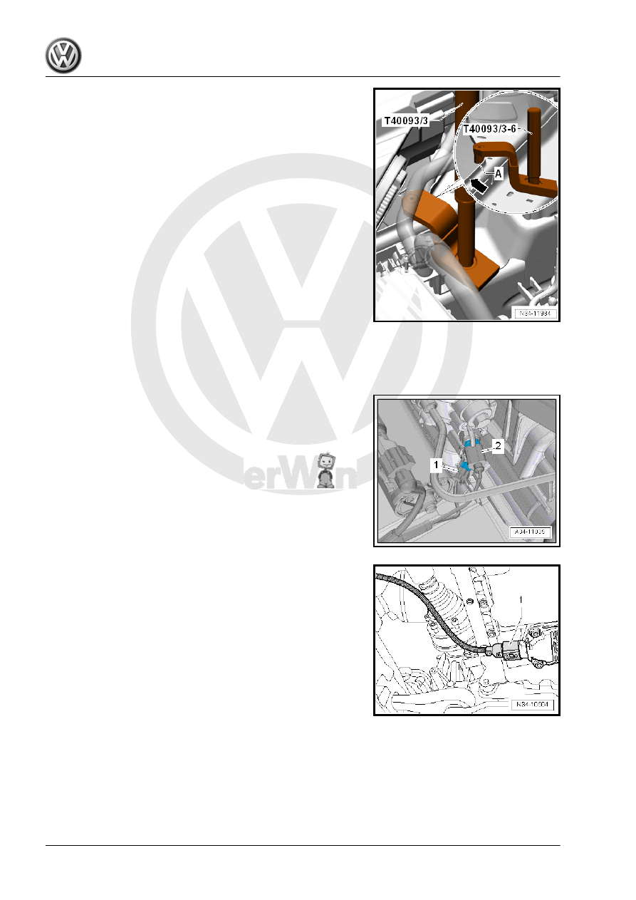
– If present, remove wires from the front area of the tab on the

longitudinal member -arrow-. Do not disconnect line system.

– Position the -T40093/3-6- on the right longitudinal member.
– If necessary, carefully unclip the A/C system pipe in the front

area. Do not disconnect the line system. Refer to ⇒  Heating,

Ventilation and Air Conditioning; Rep. Gr.  87 ; Refrigerant

Circuit; System Overview - Refrigerant Circuit .

• The -T40093/3-6- locks with the pins -A- behind the tab on the

longitudinal member -arrow-.

– Install the -T40093/3- .
– Connect the -T40093/3- over the -T40091/1- with the

-10-222A- and tension it (refer to the previous illustration).

• The -T40091/1- must be flush with the -T40091/3- and the -

T40093/3- (refer to the previous illustration).

– Then engage the -T40093/3- in the lifting eyes, as shown.
– Pretension the engine/transmission assembly and -10-222A-

via the -T40093/3- .

– Disconnect the front left connectors from the transmission:
1 - Transmission for vehicles with start/stop system: Transmis‐

sion Neutral Position Sensor - G701-

2 - Back-Up Lamp Switch - F4-
– Remove the noise insulation. Refer to ⇒  Body Exterior; Rep.

Gr.  66 ; Noise Insulation; Overview - Noise Insulation .

– Remove the lower section of the left front wheel housing liner.

Refer to ⇒  Body Exterior; Rep. Gr.  66 ; Wheel Housing Liner;

Front Wheel Housing Liner, Removing and Installing .

– Remove the starter. Refer to ⇒  Electrical Equipment; Rep. Gr. 

27 ; Starter; Starter, Removing and Installing .

– Disconnect the connector -1- from the Oil Level Thermal Sen‐

sor - G266- .

– Remove the subframe and steering gear. Refer to ⇒  Suspen‐

sion, Wheels, Steering; Rep. Gr.  40 ; Subframe; Subframe

with Steering Gear, Removing and Installing .

– Remove the drive axle heat shield -arrows- (if equipped). Re‐

fer to ⇒  Suspension, Wheels, Steering; Rep. Gr.  40 ; Drive

Axle; Drive Axle, Removing and Installing .

– Remove the drive axles from the flange shafts and tie them up

as high as possible. Be careful not to damage the surface pro‐

tection. Refer to ⇒  Suspension, Wheels, Steering; Rep. Gr. 

40 ; Drive Axle; Drive Axle, Removing and Installing .

Caution

There is a danger of causing damage to the decoupling ele‐

ment.

♦ Pay attention to ⇒  Engine Mechanical, Fuel Injection and

Ignition; Rep. Gr.  26 ; Emissions Control; Overview -

Emissions Control .

– Disconnect the exhaust system behind the particulate filter.

Refer to ⇒  Engine Mechanical, Fuel Injection and Ignition;

Rep. Gr.  26 ; Exhaust Pipes/Mufflers; Overview - Muffler .

– If present, remove nut -arrow- and ground cable.

– Remove the bolts -arrows- from the transmission mount.

– Turn the spindles on the -10-222A- and lower the transmission

to dimension -a-.

• Dimension -a- = 60 mm

– Remove the bolts -arrows- and then remove the transmission

bracket from the transmission.

– Remove the bolts -2- from the transmission/engine connec‐

tion.

The transmission to engine connection bolts -1 and 3- will be re‐

moved later in the procedure.

Align the -3282- with the -3282/33- in order to remove the trans‐

mission.
– Align the arms of the -3282- so that they match up with the

holes in the Adjustment Plate .

– Install the Support Elements -A- as illustrated on the

-3282/33- .

– Install the Mounting Element -C- instead of the -3282/29- .

– Align the -3282/33- so that it is parallel to the transmission.
– Install the -10-222A/29- into the rear hole in the transmission

for the pendulum support bolt.

– Secure the -VW771/40- inside the threaded hole in the trans‐

mission housing as illustrated.

– Secure the transmission on the -3282- using the bolt (M10×20)

-A-.

The drift -B- must be flush at the bottom with the guide on the

-3282- -arrow-.
– Position the -VAS6931- under the vehicle. The arrow on the

adjusting plate points in direction of travel.

– Remove the engine/transmission connecting bolt -C-.

– Remove the last transmission to engine connecting bolt

-arrow-.

– Separate the transmission from the engine (alignment

sleeves).

– Carefully lower the transmission while guiding the right flange

shaft past the hole -arrow 1- on the intermediate plate and the

flywheel -arrow 2-.

Note

Pay attention to the lines when lowering the transmission.

Install the transmission. Refer to

⇒ “2.2.1 Transmission, Installing, Vehicles with Turbo Diesel En‐

gine”, page 92

2.1.2

Transmission, Removing, Vehicles with

Gasoline Engine

Special tools and workshop equipment required
♦ Engine Support Bridge - 10-222A-
♦ Engine Support Bridge - Engine Support 29 - 10-222A/29-
♦ Engine Support Bridge - Engine Support 18 - 10-222A/18-
♦ If necessary Engine/Gearbox Support Shackle (2 pc.) -

10-222A/12-

♦ Transmission Support - 3282-
♦ Transmission Support - Pins 29 - 3282/29-
♦ Transmission Support - Mounting Plate 33 - 3282/33-
♦ Transmission Support Jig - 3336- to transport the transmis‐

sion.

♦ Torque Wrench 1331 5-50Nm - VAG1331-
♦ Torque Wrench 1332 40-200Nm - VAG1332-
♦ Engine and Gearbox Jack - VAS6931-
♦ Slide Hammer Set - Adapter 40 - VW771/40-
♦ Engine Support Brackets - T40093/3-6- (quantity 2)
♦ Engine Support Bridge - Special Hook (2 pc.) - 10-222A/20-
♦ Engine Support - Basic Set - Square Pipe - T40091/1- (quan‐

tity 2)

♦ Engine Support - Basic Set - Movable Joint - T40091/3- (quan‐

tity 2)

♦ Engine Support - Supplement Kit - Spindle - T40093/3- (quan‐

tity 2) from the Engine Support - Supplement Kit - T40093A-


Content   ..  500  501  502  503   ..