Volkswagen Golf / Golf GTI / Golf Variant. Manual - part 464


  Index      Volkswagen     Volkswagen Golf / Golf GTI / Golf Variant - service repair manual 2013 year


Search            copyright infringement  


Content   ..  462  463  464  465   ..


Volkswagen Golf / Golf GTI / Golf Variant. Manual - part 464


3

Transmission, Removing and Instal‐

ling

⇒ “3.1 Transmission, Removing”, page 72

 .

⇒ “3.2 Transmission, Installing”, page 91

 .

⇒ “3.3 Transmission Tightening Specifications”, page 96

 .

3.1

Transmission, Removing

⇒ “3.1.1 Transmission, Removing, Vehicles with Gasoline En‐

gine”, page 72
⇒ “3.1.2 Transmission, Removing, Vehicles with Turbo Diesel

Engine”, page 81

3.1.1

Transmission, Removing, Vehicles with

Gasoline Engine

Brief description
The transmission is removed downward separately.
»From above«:
The battery, air filter and starter are removed. Engine and trans‐

mission are supported before the left subframe mount is removed.
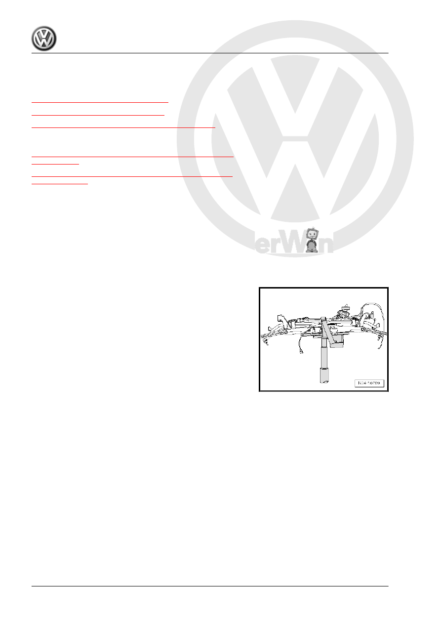
»From underneath«:
The -subframe- is removed together with the

-pendulum support- and -both control arms-. The -steering gear-

remains in the vehicle.
Both driveshafts are disconnected from the transmission and re‐

main inside the wheel bearing housings. Occasionally they will be

moved to the side, but they still remain on the vehicle.

Special tools and workshop equipment required
♦ Engine Support Bridge - 10-222A-
♦ Engine Support Bridge - Gearbox Adapter - 10-222A/29-
♦ Engine Support Bridge - Engine Support 18 - 10-222A/18-
♦ Engine/Gearbox Support Shackle (2 pc.) - 10-222A/12- (quan‐

tity 2)

♦ Transmission Support - Pins 29 - 3282/29-
♦ Transmission Support - 3282-
♦ Engine and Gearbox Jack - VAS6931-
♦ Transmission Support - Mounting Plate 42A - 3282/42A-
♦ Hose Clamps - Up To 25 mm - 3094-
♦ Tensioning Strap - T10038-
♦ Engine Bung Set - VAS6122-
♦ Insert Tool - 18mm - T10179-
♦ Socket - Xzn 14 - T10061-

♦ Engine Support - Basic Set Square Pipe - T40091/1- (quantity

2)

♦ Engine Support - Basic Set Movable Joint - T40091/3- (quan‐

tity 2)

♦ Engine Support - Supplement Kit Spindle - T40093/3- (quan‐

tity 2) from the Engine Support - Supplement Kit - T40093A-

♦ Engine Support Brackets - T40093/3-6- (quantity 2)

Removing
– Lift the vehicle, all four mounts from lifting platform at the same

height.

– Move the selector lever into »P«.
– Remove the engine cover. Refer to ⇒  Rep. Gr.  10 ; Engine

Cover; Engine Cover, Removing and Installing .

– Remove the air filter housing. Refer to ⇒  Rep. Gr.  24 ; Air

Filter; Air Filter Housing, Removing and Installing .

– Remove the battery and the battery tray -1- -arrows-. Refer to

⇒  Electrical Equipment; Rep. Gr.  27 ; Battery, Removing and

Installing .

– Remove the selector lever cable from the transmission

-arrows-.

Note

Use pliers to remove the lock washer from the cable bracket.

Do not use a sharp-edged lever. Otherwise the selector lever

cable could get damaged.

Remove the cable bracket -2- from the transmission, if nec‐

essary. Remove the bolts -1- and the lock washer -3-.

Replace the bolts -1- and the lock washers.

Bolt tightening specification -1- 20 Nm +90°.

Caution

Risk of damaging the selector lever cable.

♦ Remove the selector level cable from the cable bracket

when lowering transmission.

♦ Do not bend or kink the selector lever cable.

– Remove the charge air pipe. Refer to ⇒  Rep. Gr.  21 ; Over‐

view - Charge Air System .

– Place a lint-free cloth on to transmission fluid cooler and trans‐

mission to absorb escaping coolant.

WARNING

Risk of scalding due to hot steam and hot coolant.

♦ The cooling system is under pressure when the engine is

warm.

♦ Reduce the pressure by covering the coolant reservoir cap

with cloths and carefully opening.

– Clamp the coolant hose with the Hose Clamps - Up To 25mm

- 3094- .

– Loosen the hose clamps -arrows- and remove the coolant ho‐

ses from the transmission fluid cooler.

– Remove the bolts -1- and move the Transmission Coolant

Valve - N488- to the side. Tightening specification. Refer to

⇒ “3.3 Transmission Tightening Specifications”, page 96

 .

– Seal the transmission fluid cooler connections with plugs tak‐

en from Engine Bung Set - VAS6122- .

– Remove the starter -A-. Refer to ⇒  Electrical Equipment; Rep.

Gr.  27 ; Starter; Starter, Removing and Installing .

Remove the »lower« bolt first.

Caution

There is a risk of damaging the DSG Transmission Mecha‐

tronic - J743- with static electricity.

♦ Do not touch contacts in DSG Transmission Mechatronic

- J743- connector with hands.

– To discharge any static electricity, touch the vehicle ground

with hand (without wearing a glove). Refer to 

⇒ page 7

 .

– Release the Mechatronic connector twist lock -1- by turning it

»counter-clockwise« and remove the connector.

– Remove all upper engine/transmission connecting bolts.

These tools are suitable for this.


Content   ..  462  463  464  465   ..