Volkswagen Golf / Golf GTI / Golf Variant. Manual - part 462


  Index      Volkswagen     Volkswagen Golf / Golf GTI / Golf Variant - service repair manual 2013 year


Search            copyright infringement  


Content   ..  460  461  462  463   ..


Volkswagen Golf / Golf GTI / Golf Variant. Manual - part 462


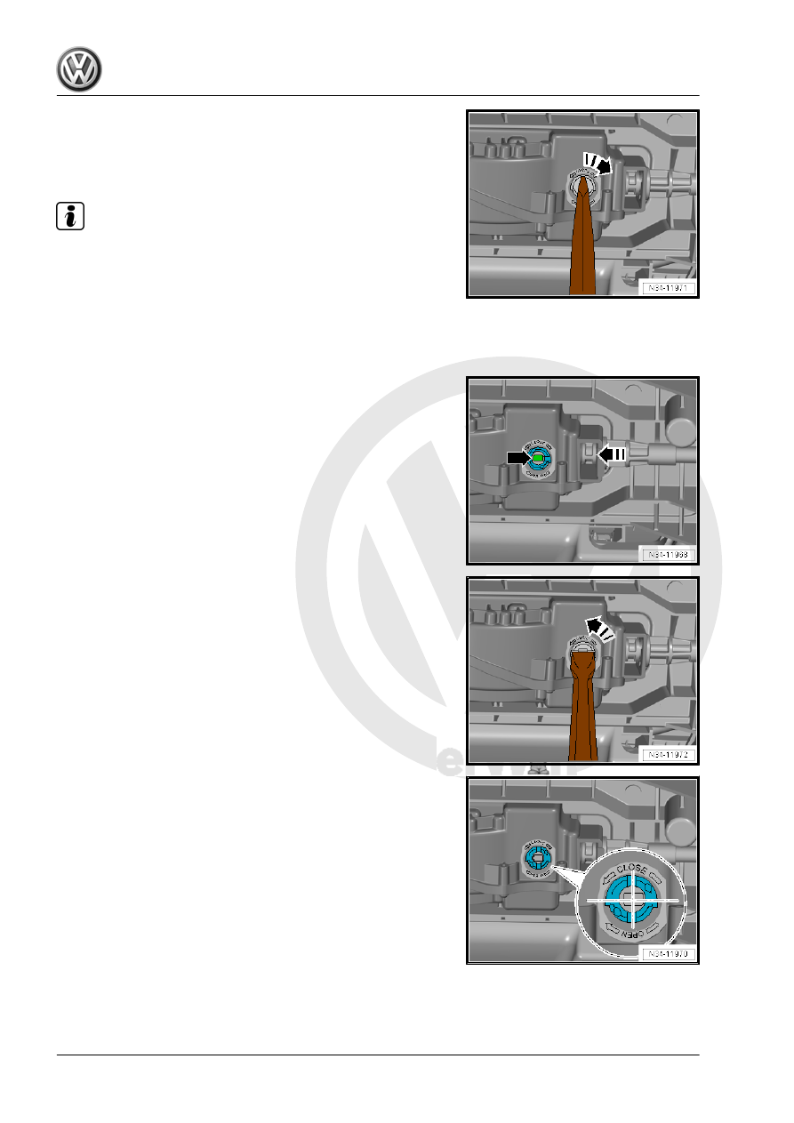
– Insert a large screwdriver into the grooves on the locking

mechanism and turn 90° in the direction of the -arrow-.

– Pull the cable from the selector mechanism and remove.
Installing

Note

Do not bend or kink the selector lever cable.

Do not lubricate the selector lever cable.

After installing check the selector lever cable for ease of move‐

ment.

• The selector lever for the gearshift mechanism is in the “N”

position. The cable can only be locked in this position.

– Guide the cable in the selector mechanism in direction of

-arrow- until the locking mechanism -arrow- is visible.

– Turn the locking mechanism 90° in the direction of the

-arrow- with a large screwdriver.

– The cable is correctly locked when the grooves on the locking

mechanism are at a right angle to the cable.

– Install new lock washer -arrow- and replace the plugs.

– Remove the cable from the transmission and secure using a

new lock washer -B-. Do not install the lock washer -A- yet. It

will be installed after the cable is checked and adjusted.

– Install the heat shield under the gearshift mechanism. Refer

to ⇒  Body Exterior; Rep. Gr.  66 ; Molding/Trim/Extensions/

Trim Panels; Floor Heat Shield, Removing and Installing .

– Adjust the selector lever cable. Refer to

⇒ “2.8 Selector Lever Cable, Checking and Adjusting”,

page 68

 .

– Check the selector mechanism. Refer to

⇒ “2.7 Gearshift Mechanism, Checking”, page 67

 .

– Install the air filter housing. Refer to ⇒  Engine Mechanical,

Fuel Injection and Ignition; Rep. Gr.  24 ; Air Filter; Air Filter

Housing, Removing and Installing or ⇒  Rep. Gr.  23 ; Air Filter;

Air Filter Housing, Removing and Installing

2.6.2

Selector Lever Cable, Removing and In‐

stalling, ECS

Caution

This procedure contains mandatory replaceable parts. Refer

to component overview prior to starting procedure.

Mandatory Replacement Parts
♦ Lock Washers - Selector Lever Cable
♦ Cover - Selector Mechanism
Removing
– Remove the air filter housing:
♦ Gasoline engine. Refer to ⇒  Engine Mechanical, Fuel Injec‐

tion and Ignition; Rep. Gr.  24 ; Air Filter; Air Filter Housing,

Removing and Installing .

♦ Diesel engine. Refer to ⇒  Rep. Gr.  23 ; Air Filter; Air Filter

Housing, Removing and Installing .

Loosen the adjusting screw -arrow-.
– Remove the lock washers -A and B-. The lock washers must

later be replaced when adjusting selector lever cable.

Use pliers to remove the lock washer -B-. Do not use a sharp-

edged lever. Otherwise the selector lever cable could get dam‐

aged.
– Position the selector lever on the selector mechanism in the

“N” position. The cable can only be loosened in this position.

– Remove the center tunnel heat shield under the gearshift

mechanism. Refer to ⇒  Body Exterior; Rep. Gr.  66 ; Molding/

Trim/Extensions/Trim Panels; Floor Heat Shield, Removing

and Installing .

– Pry up the lower cover from the selector mechanism in the

direction of -arrow- and remove.

Note

Do not reuse the cover. Always replace after removing.

– Release the cable as shown with a screwdriver and remove

from the selector lever in the direction of -arrows-.

– Remove the lock washer in the direction of -arrow-.
Always replace the lock washer.
– Pull the cable from the selector mechanism and remove.
Installing
Install in reverse order of removal. Note the following:

Note

Do not bend or kink the selector lever cable.

Do not lubricate the selector lever cable.

After installation, the selector lever cable movement must be

checked and adjusted.

• The selector mechanism selector lever is in the “N” position.
– Guide the cable on the selector mechanism, inset in the se‐

lector lever and install new lock washer.

– Remove the cable from the transmission and secure using a

new lock washer -B-. Do not install the lock washer -A- yet. It

will be installed after the cable is checked and adjusted.

– Install the heat shield under the gearshift mechanism. Refer

to ⇒  Body Exterior; Rep. Gr.  66 ; Molding/Trim/Extensions/

Trim Panels; Floor Heat Shield, Removing and Installing .

– Adjust the selector lever cable. Refer to

⇒ “2.8 Selector Lever Cable, Checking and Adjusting”,

page 68

 .

– Check the selector mechanism. Refer to

⇒ “2.7 Gearshift Mechanism, Checking”, page 67

 .

– Install the air filter housing:
♦ Gasoline engine. Refer to ⇒  Engine Mechanical, Fuel Injec‐

tion and Ignition; Rep. Gr.  24 ; Air Filter; Air Filter Housing,

Removing and Installing .

♦ Diesel engine. Refer to ⇒  Rep. Gr.  23 ; Air Filter; Air Filter

Housing, Removing and Installing .

2.7

Gearshift Mechanism, Checking

The starter does not work when the selector lever is in “R”, “D”

and “S” or in the tiptronic gate.
Over 5 km/h:
The shift lock solenoid must not block the selector lever when the

lever is in “N”. The selector lever can be moved back into a an‐

other gear.
Below 5 km/h:
The shift lock solenoid will block the selector lever approximately

1 second after the lever is moved into “N”. The selector lever can

be moved out of “N” only when the brake pedal is pressed.
Selector Lever in “P” and the Ignition Turned on

• If the brake pedal is not depressed:
The selector lever is locked and cannot be moved out of “P” when

the locking button is pressed. The shift lock solenoid blocks the

selector lever.
• If the brake pedal is depressed:
The shift lock solenoid releases the selector lever. It is possible

to shift into a gear. Slowly move the selector lever slowly from “P”

through “S”; while doing this, check whether display of selector

lever position in instrument panel insert matches actual selector

lever position.
The Selector Lever is in “N” and the Ignition is Turned On:
• If the brake pedal is not depressed:
The selector lever is locked and cannot be moved out of “N” when

the button is pressed. The shift lock solenoid blocks the selector

lever.
• If the brake pedal is depressed:
The shift lock solenoid releases the selector lever. It is possible

to shift into a gear.
Selector Level in the “Tiptronic” Position
• Move selector lever into Tiptronic gate:


Content   ..  460  461  462  463   ..