Volkswagen Golf / Golf GTI / Golf Variant. Manual - part 373


  Index      Volkswagen     Volkswagen Golf / Golf GTI / Golf Variant - service repair manual 2013 year


Search            copyright infringement  


Content   ..  371  372  373  374   ..


Volkswagen Golf / Golf GTI / Golf Variant. Manual - part 373


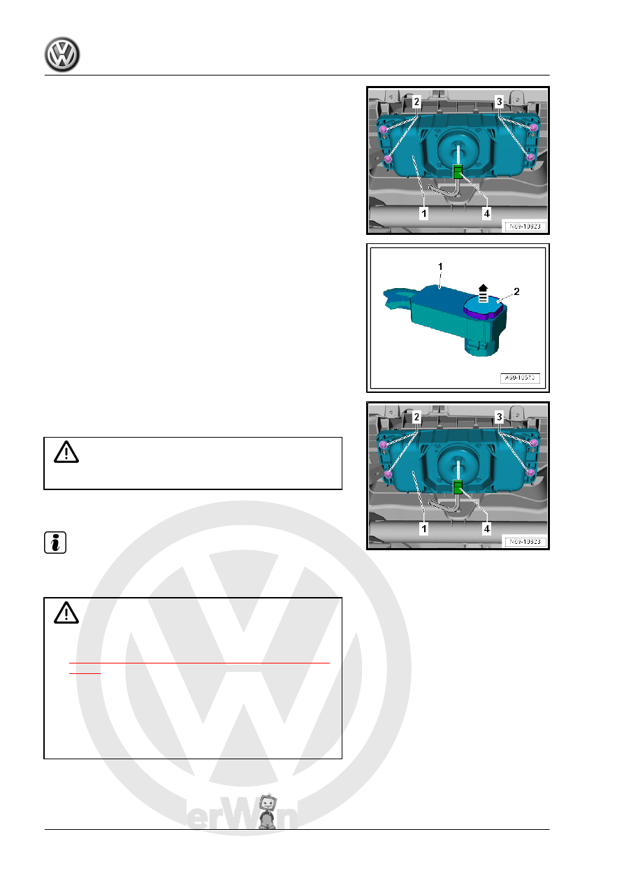
– Disconnect the connector -4- from the Front Passenger Airbag

Igniter 1 - N131- .

– To do so, release the connector lock -2- with a small screw‐

driver in direction of -arrow- and disconnect the connector

-1-.

– If equipped, disconnect the second connector for the Front

Passenger Airbag Igniter 2 - N132- in the same manner.

– Remove the bolts -2 and 3-.
– Remove the front passenger airbag -1- downward.

WARNING

Lay airbag unit so that the padding faces upward.

Installing

Note

Before installing the bolts, the bolt and nut threads in the instru‐

ment panel must be cleaned.

WARNING

♦ Observe the safety precautions for pyrotechnical compo‐

nents. Refer to

⇒ “1.2 Safety Precautions for Pyrotechnic Components”,

page 3

 .

♦ Before handling pyrotechnic components (for example,

connecting the connector), the person handling it must

“discharge static electricity”. This can be done by touching

the door striker pin, for example.

♦ Observe the airbag allocation for the instrument panel.

Refer to the Parts Catalog.

– Connect the connector -1- to the airbag igniter(s) in direction

of -arrow A-.

– Install the connector locking mechanism -2- in direction of

-arrow B-. While doing this, the connector is pushed into the

airbag igniter and locks into place.

Install in reverse order of removal while paying attention to the

following:

Note

Make sure the connectors are pushed in all the way and that

they engage audibly.

Make sure the wires are not pinched.

WARNING

The ignition must be on when connecting the battery. If pyro‐

technic components (for example, airbag, belt tensioner) are

not repaired correctly, they may deploy unintentionally after

connecting battery. There must not be anyone inside the ve‐

hicle when connecting the battery.

– Connect the battery ground cable with the ignition turned on.

Refer to ⇒  Electrical Equipment; Rep. Gr.  27 ; Battery; Bat‐

tery, Disconnecting and Connecting .

WARNING

If the ignition is not switched on after the battery is reconnected

- “indicator lamps in the instrument cluster do not light up” - the

ignition (key/button) may only be switched on when the driver

seat is positioned all the way back.

Note

If the Airbag Indicator Lamp - K75- signals a fault after installing,

check the DTC memory, erase it and check it again use the Ve‐

hicle Diagnostic Tester .

Tightening Specifications
♦ Refer to

⇒ “6.1 Overview - Front Passenger Airbag”, page 138

6.3

Front Passenger Airbag Deactivation

Key Switch, Removing and Installing

NOT FOR NORTH AMERICAN MARKET

Note

These versions are not installed on vehicles that were released

in the USA.

Removing
– Switch off the ignition.
– Remove the instrument panel side cover. Refer to

⇒ “3.2 Instrument Panel Side Cover, Removing and Installing”,

page 211

 .

– Press the catch -1- in the direction of the -arrow- until the con‐

nector disengages.

– Disconnect the connector -2-.
– Release the springs -3- and -5-.
– Push the Front Passenger Airbag Deactivation Key Switch -

E224- -item 4- out of the key switch housing.

Installing
Install in reverse order of removal while paying attention to the

following:

Note

Make sure the connectors are pushed in all the way and that

they engage audibly.

Make sure the wires are not pinched.

– Make sure the Front Passenger Airbag Deactivation Key

Switch - E224- clicks into the housing.

6.4

Front Passenger Airbag -Disabled- Indi‐

cator Lamp - K145- , Removing and In‐

stalling

Note

The Front Passenger Airbag -Disabled- Indicator Lamp - K145- is

integrated in one component with the Emergency Flasher Switch

- EX3- and cannot be replaced separately if faulty.

– Emergency Flasher Switch - EX3- , removing and installing.

Refer to ⇒  Electrical Equipment; Rep. Gr.  96 ; Controls;

Emergency Flasher Switch EX3, Removing and Installing .

7

Side Airbags

⇒ “7.1 Overview - Front Side Airbag”, page 143
⇒ “7.2 Overview - Rear Side Airbag”, page 144
⇒ “7.3 Front Side Airbag with Igniter, Removing and Installing”,

page 145
⇒ “7.4 Rear Side Airbag with Igniter, Removing and Installing”,

page 146

7.1

Overview - Front Side Airbag

1 - Backrest Frame
2 - Hook

❑ for securing the side air‐

bag to the backrest

frame

3 - Front Side Airbag

❑ Driver side: with the

Driver Thorax Airbag Ig‐

niter - N199-

❑ Front passenger side:

with Front Passenger

Thorax Airbag Igniter -

N200-

WARNING

Observe the safety pre‐

cautions  for  pyrotechni‐

cal components. Refer to

⇒  “1.2  Safety  Precau‐

tions  for  Pyrotechnic

Components”, page 3

 .

❑ Removing and instal‐

ling. Refer to

⇒ “7.3 Front Side Airbag

with Igniter, Removing

and Installing”,

page 145

 .

4 - Screw

❑ 8 Nm
❑ Replace after removing

5 - Wire

❑ From Driver Thorax Air‐

bag Igniter - N199- /

Front Passenger Thorax Airbag Igniter - N200-


Content   ..  371  372  373  374   ..