Volkswagen Golf / Golf GTI / Golf Variant. Manual - part 372
Tightening Specifications
♦ Refer to
⇒ “5.1 Overview - Driver Side Airbag”, page 131
5.3
Airbag Connector, Replacing
Removing
WARNING
Observe the safety precautions for pyrotechnical components.
Refer
to
⇒ “1.2 Safety Precautions for Pyrotechnic Components”, page
.
– Remove the driver side airbag. Refer to
⇒ “5.2 Airbag Unit with Igniter, Removing and Installing”, page
.
Equipment Levels: Steering Wheel without Multifunction
WARNING
Before handling pyrotechnic components (for example, dis‐
connecting the connector), the person handling it must “dis‐
charge static electricity”. This can be done by touching the door
striker pin, for example.
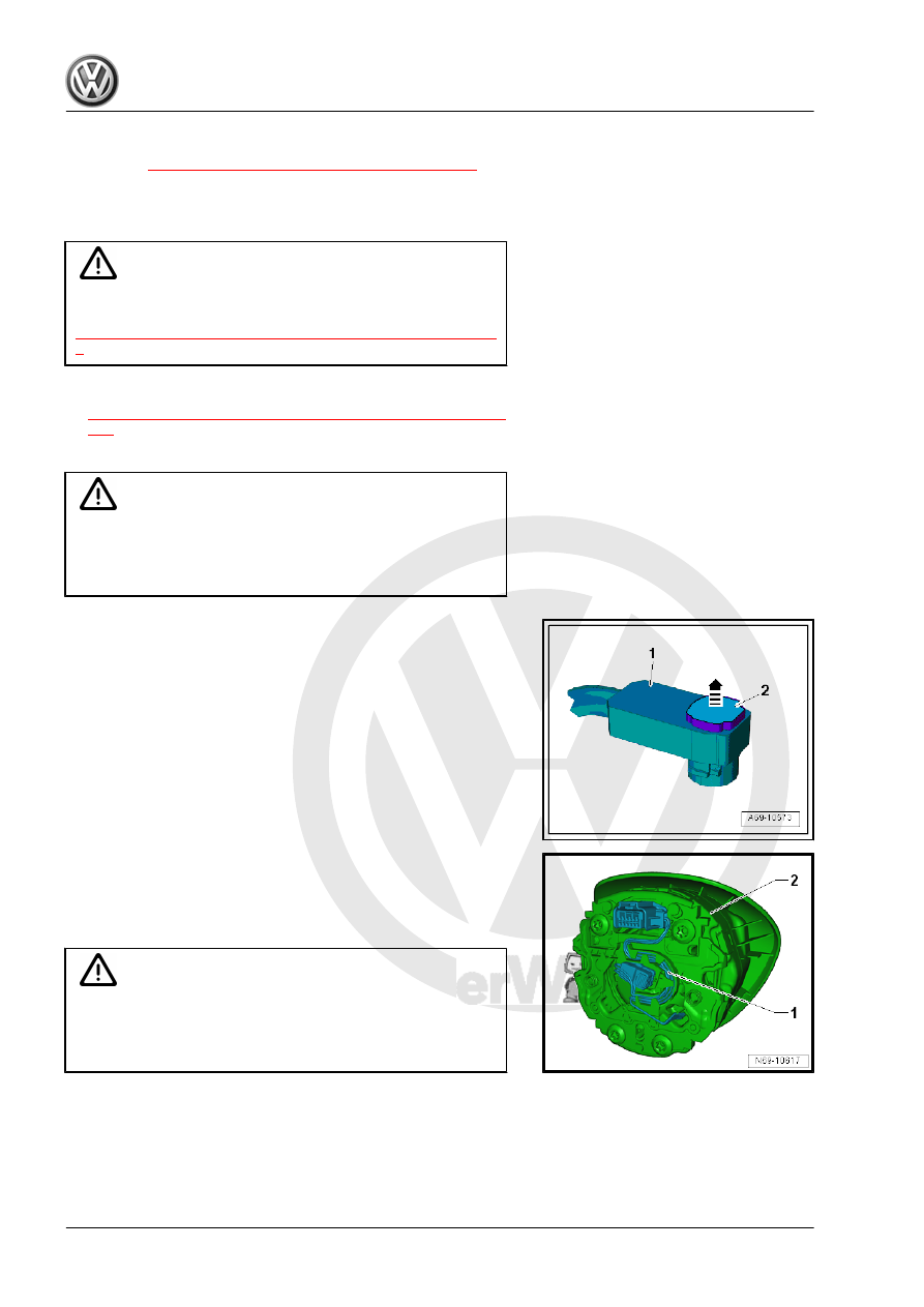
– Release the connector lock -2- using a small screwdriver in
direction of -arrow- and remove the connector -1- from the
Driver Airbag Igniter - N95- .
– Disconnect the connectors from the wiring harness -1-.
– Disengage the wiring harness at the brackets and remove
from the driver side airbag -2-.
Equipment Levels: Steering Wheel with Multifunction
WARNING
Before handling pyrotechnic components (for example, dis‐
connecting the connector), the person handling it must “dis‐
charge static electricity”. This can be done by touching the door
striker pin, for example.