Volkswagen Golf / Golf GTI / Golf Variant. Manual - part 228


  Index      Volkswagen     Volkswagen Golf / Golf GTI / Golf Variant - service repair manual 2013 year


Search            copyright infringement  


Content   ..  226  227  228  229   ..


Volkswagen Golf / Golf GTI / Golf Variant. Manual - part 228


1.12

Gas-Filled Strut, Removing and Installing

Removing
– Open and support the hood.

WARNING

Proceed carefully when reusing a gas-filled strut. Do not pry

the spring clip completely out of the ball socket or the spring

clip will be damaged. The gas-filled strut will spring out of the

mount, resulting in damage or injury to the technician.

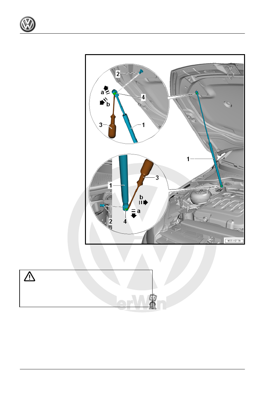
– Reach under the spring clip -4- with a small screwdriver -3-.
– Lift the spring clip -4- just far enough so that the spring clip can

be moved over the ball socket in direction of -arrow a-.

– Remove the gas-filled strut -1- from the ball stud -2- in direction

of -arrow b-.

After removing the gas-filled strut -1- immediately slide the spring

clip -4- back again.

– The gas-filled strut must be vented when disposing of it. Refer

to 

⇒ “1.13 Gas-Filled Strut, Venting”, page 45

 .

Installing
– Push the gas-filled strut -1- onto the ball stud -2-.
Tightening Specifications

Component

Tightening Specification

Ball stud to the hood or body

20 Nm

1.13

Gas-Filled Strut, Venting

– Clamp the area -x- of the gas strut in the vise, area x = 50 mm.

WARNING

Wear protective eyewear when sawing.
Cover the area of the saw cut with a cleaning cloth.
Dispose of the oil and cleaning cloths properly.

– Cut open the gas-filled strut cylinder within the first third of the

total cylinder length using the piston rod side of the cylinder as

a reference point.

1.14

Release Cable, Removing and Installing

Removing
– Open the hood.
– Remove the release lever. Refer to

⇒ “1.7 Hood Release Lever, Removing and Installing”,

page 35

 .

– Remove the release cable -6- from the bracket -5- in direction

of -arrow a-.

– Remove the release cable coupling -2- from the support -7- in

direction of -arrow f-.

– Slightly pull out the release cable -1- in direction of -arrow b-.
– Open the cap of the release cable coupling in direction of

-arrow c-.

– Release the release cable -1- in direction of -arrow d- and re‐

move from the release cable coupling -2- in direction of

-arrow e-.

Note

To remove and install the release cable -3-, the support -7- is removed. Refer to

⇒ “1.1 Overview - Lock Carrier”, page 1

 .

Installing

Note

When the release cable -3- is not removed from the bracket, the release cable -1- disengages further when

installing it in the release cable coupling -2-.

The hood then cannot be opened.

– Engage the release cable -1- in the release cable coupling

-2- in direction of -arrow b-.

– Pull the release cable slightly off the release cable coupling in

direction of -arrow c-.

– Close the release cable coupling in direction of -arrow d-.
– Push the release cable -1- in the release cable coupling in

direction of -arrow e-.

– Secure the release cable coupling -2- on the support -7- in

direction of -arrow f-.

– Install the release cable -6- in the bracket -5- in direction of

-arrow a-.


Content   ..  226  227  228  229   ..