Volkswagen Golf / Golf GTI / Golf Variant. Manual - part 163
DTC /
Descrip‐
tion
Monitor
Strategy
Descrip‐
tion
Malfunction Crite‐
ria and Threshold
Value
Secondary Parame‐
ters with Enable
Conditions
Monitor‐
ing Time
Length
MIL Il‐
lum.
Component Diag‐
nostic Procedure
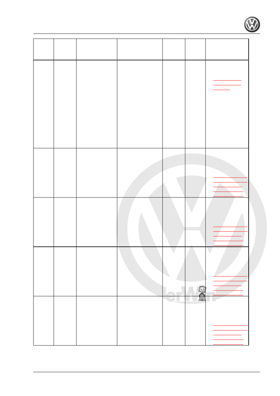
P169A
Loading
Mode
Active
ECM:
Transport
Mode
Function
Monitor‐
ing: Mode
Change
• Transport
mode active
• Vehicle speed < 3
mph
• Max trip mileage
since initial vehi‐
cle start-up <
62.15 miles
• During ECM keep
alive-time after
ignition off engine
speed 0 RPM
• Production mode
not active
• For hybrid:
• Drive motor off
• 0.01 s
• Con‐
tinu‐
ous
• 1
DCY
– Perform readi‐
ness check. Re‐
fer to
P2004
Intake
Manifold
Runner
Control
Stuck
Open
Bank 1
Intake
Manifold
Runner
Flap Ac‐
tuator
Stuck
Open
• Signal voltage
> 1.89 V
• For time >= 1.5
s
• Flap commanded
off
• Time after engine
start > 5.0 s
• 0.2 s
• Con‐
tinu‐
ous
• 2
DCY
– Check the In‐
take Manifold
Runner Control
Valve - N316- .
Refer to
.
P2006
Intake
Manifold
Runner
Control
Stuck
Closed
Bank 1
Intake
Manifold
Runner
Flap Ac‐
tuator
Stuck
Close
• Signal voltage
< 3.10 V
• For time >= 1.5
s
• Flap commanded
on
• Time after engine
start > 5.0 s
• 0.2 s
• Con‐
tinu‐
ous
• 2
DCY
– Check the In‐
take Manifold
Runner Control
Valve - N316- .
Refer to
.
P2008
Intake
Manifold
Runner
Control
Circuit/
Open
Bank 1
Intake
Manifold
Runner
Flap Ac‐
tuator
Open Cir‐
cuit
• Output voltage
lower range
1.92 – 2.21 V
• Output voltage
upper range
(hardware val‐
ues) 2.85 –
3.25 V
• Engine running
• Actuator com‐
manded off
• 2.0 s
• Con‐
tinu‐
ous
• 2
DCY
– Check the In‐
take Manifold
Runner Control
Valve - N316- .
Refer to
.
P2009
Intake
Manifold
Runner
Control
Circuit
Low
Bank 1
Intake
Manifold
Runner
Flap Ac‐
tuator
Short To
Ground
• Output voltage
(hardware val‐
ues) < 1.92 –
2.21 V
• Engine running
• Actuator com‐
manded off
• 2.0 s
• Con‐
tinu‐
ous
• 2
DCY
– Check the In‐
take Manifold
Runner Control
Valve - N316- .
Refer to
.
GTI 2014 ➤
Generic Scan Tool - Edition 04.2015
3. Diagnosis and Testing
325