Volkswagen Golf / Golf GTI / Golf Variant. Manual - part 105
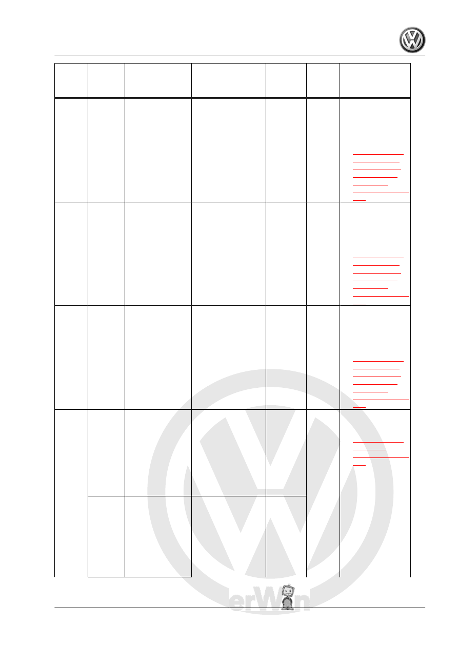
DTC /
Descrip‐
tion
Monitor
Strategy
Descrip‐
tion
Malfunction Crite‐
ria and Threshold
Value
Secondary Parame‐
ters with Enable
Conditions
Monitoring
Time
Length
MIL Il‐
lum.
Component Diag‐
nostic Procedure
P025A
Fuel
Pump
Module
"A" Con‐
trol Cir‐
cuit/
Open
Fuel
Pump
Open Cir‐
cuit
• Signal voltage,
lower range >
1.92 – 2.21 V
• And
• Signal voltage,
upper range
(hardware val‐
ues) < 2.84 –
3.25 V
• Commanded
PWM 9.80 –
90.20 %
• Fuel pump com‐
manded off
• 0.5 s
• Contin‐
uous
• 2
DCY
– Check the Fuel
Pump Control
Module - J538- /
Fuel Delivery
Unit - GX1- . Re‐
fer to
P025C
Fuel
Pump
Module
"A" Con‐
trol Cir‐
cuit Low
Fuel
Pump
Short To
Ground
• Signal voltage
(hardware val‐
ues) < 1.92 –
2.21 V
• Commanded
PWM 9.80 –
90.20 %
• Fuel pump com‐
manded off
• 3.0 s
• Contin‐
uous
• 2
DCY
– Check the Fuel
Pump Control
Module - J538- /
Fuel Delivery
Unit - GX1- . Re‐
fer to
P025D
Fuel
Pump
Module
"A" Con‐
trol Cir‐
cuit High
Fuel
Pump
Short To
Battery
Voltage
• Power stage
temperature >
160.0 – 200.0°
C
• Or
• Signal current
(hardware val‐
ues) > 0.1 –
0.18 A
• Commanded
PWM 9.80 –
90.20 %
• Fuel pump com‐
manded on
• 0.5 s
• Contin‐
uous
• 2
DCY
– Check the Fuel
Pump Control
Module - J538- /
Fuel Delivery
Unit - GX1- . Re‐
fer to
P0261
Cylinder
1 Injec‐
tor "A"
Circuit
Low
Injection
Valves
Short To
Ground
• Fault pattern
for short to
ground via
powerstage di‐
agnosis detec‐
ted
• Injector voltage
< 2.0 V
• Engine stop not
active
• ECT @ cylinder
head >= -30° C
• Engine speed <
7,000 RPM
• Injection time >=
0.0 s
• 8,640.0°
CRK
• Contin‐
uous
• 2
DCY
– Check the Fuel
Injectors . Refer
to
Injection
Valves
Short To
Ground
(High
Side)
• Injector driver
voltage < 2 V
• And
• Injector driver
high side
switch current
(hardware val‐
ues) > 25 A
• Engine running
• ECT @ cylinder
head >= -30° C
• Engine speed <
7,000 RPM
• Injection time >=
0.0 s
• 720°
CRK
• Contin‐
uous
GTI 2014 ➤
Generic Scan Tool - Edition 04.2015
3. Diagnosis and Testing
93