Volkswagen Golf / Golf GTI / Golf Variant. Manual - part 73


  Index      Volkswagen     Volkswagen Golf / Golf GTI / Golf Variant - service repair manual 2013 year


Search            copyright infringement  


Content   ..  71  72  73  74   ..


Volkswagen Golf / Golf GTI / Golf Variant. Manual - part 73


3.3.2

Anti-Theft Alarm System Sensor -

G578- , Removing and Installing, Ver‐

sion with Four Screws

Special tools and workshop equipment required
♦ Trim Removal Wedge - 3409-

Caution

Risk of damaging the component surfaces.

♦ When positioning a prying tool, put commercially available

adhesive tape over the component in the visible area.

Removing
– Turn off the ignition and all electrical equipment.
– Remove the ignition key, if equipped.
– Remove the Front Interior Lamp - WX1- . Refer to

⇒ “2.30 Front Interior Lamp/Reading Lamp, Removing and In‐

stalling”, page 275

 .

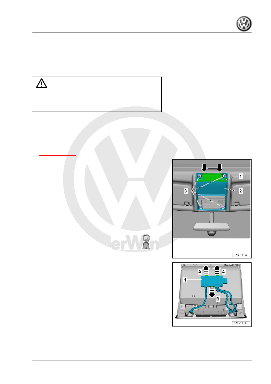
– Using the -3409- pry the cover -1- in the area of the -arrows-.
– Remove the screws -3-.
– Remove the roof module -2-.
– Disengage the connector and disconnect.

– Release the mounting tabs in the direction of the arrows

-A and B-.

– Remove the Anti-Theft Alarm System Sensor - G578- -1- from

the roof module.

– Release the mounting tabs in the direction of the

-arrows A and B-.

– Remove the individual sensor -1- from the roof module.
Installing
Install in the reverse order of removal while paying attention to

the following:
If the Anti-Theft Alarm System Sensor - G578- is being replaced,

then it must be adapted using the Vehicle Diagnostic Tester .
– Perform a function test.
Tightening Specifications
♦ Refer to 

⇒ “3.1 Overview - Interior Monitoring”, page 278

4

Driver Assistance Systems Front

Camera

⇒ “4.1 Driver Assistance Systems Front Camera, Removing and

Installing”, page 283

4.1

Driver Assistance Systems Front Cam‐

era, Removing and Installing

Removing
– Turn off the ignition and all electrical equipment.
– Remove the ignition key, if equipped.
– Remove the mirror base cover. Refer to ⇒  Body Interior; Rep.

Gr.  68 ; Rearview Mirror; Overview - Rearview Mirror .

– Unclip the Driver Assistance Systems Front Camera - R242-

-2- in the direction of the -arrow A- from the clamps -1-.

– Remove the Driver Assistance Systems Front Camera - R242-

-1- in the direction of the -arrow B- from the bracket.

– Disconnect the connector -3-.
Installing
Install in the reverse order of removal while paying attention to

the following:
– Calibrate the Driver Assistance Systems Front Camera -

R242- . Refer to ⇒  Suspension, Wheels, Steering; Rep. Gr. 

44 ; Driver Assistance Systems Front Camera; Driver Assis‐

tance Systems Front Camera, Calibrating .

5

Cigarette Lighter and Socket

⇒ “5.1 Overview - Converter with Socket, 12 V-230 V”,

page 284
⇒ “5.2  Cigarette Lighter U1 , Removing and Installing”,

page 285
⇒ “5.3  Socket Illumination Bulb L42 , Removing and Installing”,

page 285
⇒ “5.4  Rear Cigarette Lighter Illumination Bulb L32 , Removing

and Installing”, page 285
⇒ “5.5  Socket U , Removing and Installing”, page 285
⇒ “5.6  Converter with Socket, 12 V-230 V U13 , Removing and

Installing”, page 285

5.1

Overview - Converter with Socket, 12 V-230 V

1 - Bracket

❑ To mount the Converter

with Socket, 12 V-230 V

- U13-

❑ Removing and instal‐

ling. Refer to

⇒ “5.6  Converter with

Socket, 12 V-230 V

U13 , Removing and In‐

stalling”, page 285

 .

2 - Screw

❑ 2 Nm
❑ Quantity: 4
❑ To secure the Converter

with Socket, 12 V-230 V

- U13- to the bracket

3 - Bolt

❑ 9 Nm
❑ Quantity: 2
❑ To secure the bracket in

the side panel

4 - Converter with Socket, 12

V-230 V - U13-

❑ Must not be opened.
❑ No repairs on the con‐

nector, on the lines and

on the 230 V socket

❑ Removing and instal‐

ling. Refer to

⇒ “5.6  Converter with

Socket, 12 V-230 V

U13 , Removing and In‐

stalling”, page 285

 .

5 - Connector

❑ 12-V input voltage


Content   ..  71  72  73  74   ..