Volkswagen Golf / Golf GTI / Golf Variant. Manual - part 58
– Remove the Blind Spot Detection Control Module - J1086- /
Blind Spot Detection Control Module 2 - J1087- with the brack‐
et -1-.
– Remove the Blind Spot Detection Control Module - J1086- /
Blind Spot Detection Control Module 2 - J1087- -2- from the
bracket -1-.
Installing
Install in the reverse order of removal while paying attention to
the following:
Note
♦
The blind spot detection calibration normally occurs automat‐
ically.
♦
Static calibration is only required when there is a DTC memory
entry.
Tightening Specifications
♦ Refer to
⇒ “13.1.1 Overview - Blind Spot Detection, Sedan”,
13.3.2
Blind Spot Detection Control Module -
J1086- / Blind Spot Detection Control
Module 2 - J1087- , Removing and In‐
stalling, Wagon
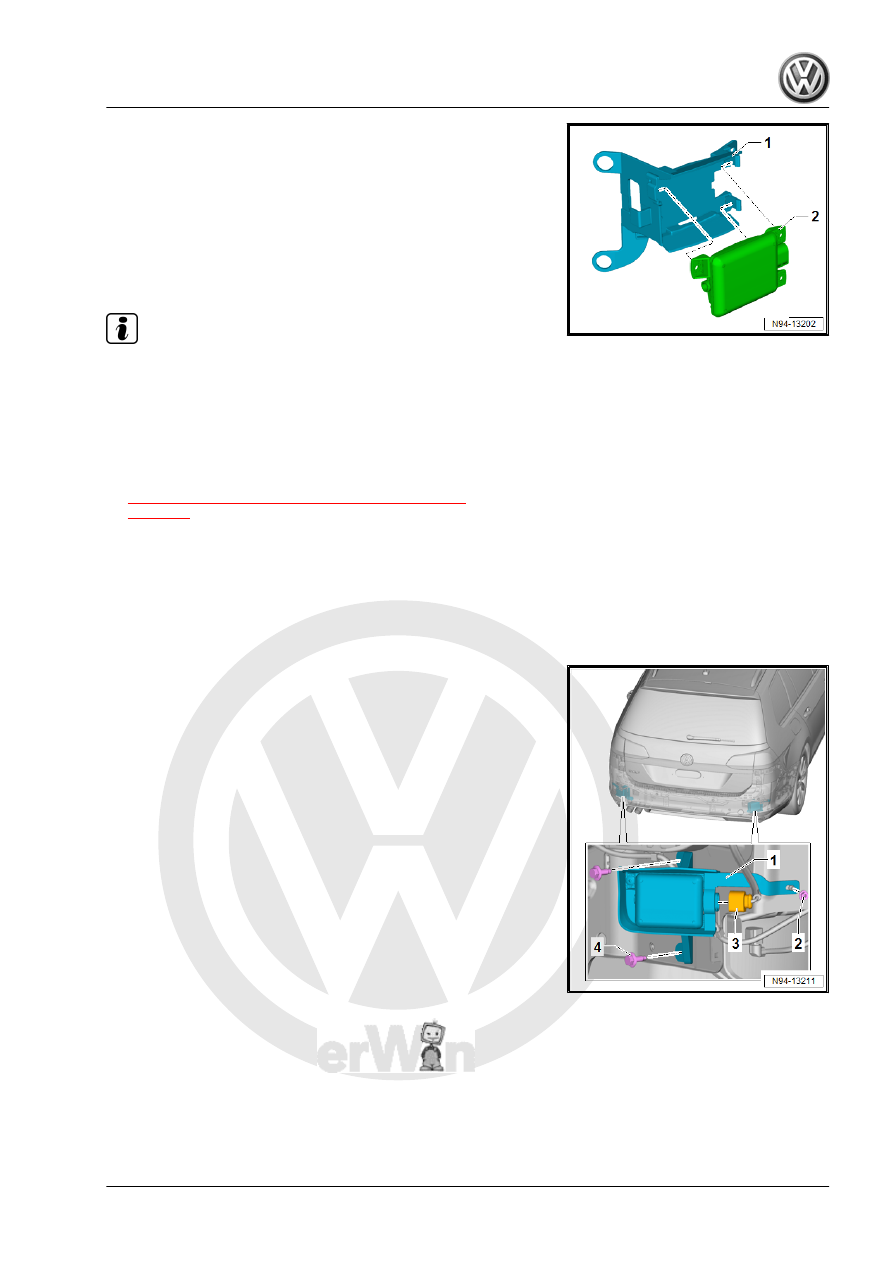
Removing
– Disconnect the connector -3-.
– Remove the nuts -2- and bolts -4-.
– Remove the Blind Spot Detection Control Module - J1086- /
Blind Spot Detection Control Module 2 - J1087- with the brack‐
et -1-.