Volkswagen Golf / Golf GTI / Golf Variant. Manual - part 45
4 - Access/Start System Interface - J965-
❑ Bracket screws (only for NAR): 2 Nm
❑ Removing and installing. Refer to
⇒ “7.3 Access/Start System Interface J965 , Removing and Installing”, page 170
7.2.2
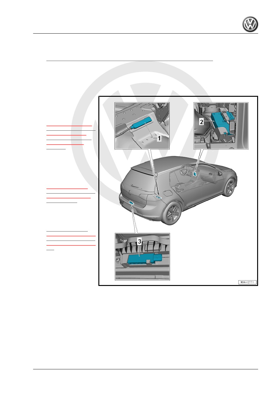
Component Location Overview - Rear Keyless Access Authorization Sys‐
tem, Sedan
1 - Access/Start System An‐
tenna In Luggage Compart‐
ment - R137-
❑ Removing and instal‐
ling. Refer to
.
2 - Access/Start System Inter‐
face - J965-
❑ Bracket screws (only for
NAR): 2 Nm
❑ Removing and instal‐
ling. Refer to
.
3 - Access/Start System An‐
tenna in Rear Bumper - R136-
❑ Removing and instal‐
ling. Refer to