Volkswagen Golf / Golf GTI / Golf Variant. Manual - part 12
– Remove the Starter - B- -2- upward.
Installing
Install in the reverse order of removal while paying attention to
the following:
– Connect the Battery - A- . Refer to
⇒ “1.3 Battery, Disconnecting and Connecting”, page 9
Tightening Specifications
♦ Refer to
⇒ “3.1.3 Overview - Starter, Vehicles with DSG Transmission
3.2.4
Starter, Removing and Installing, Vehi‐
cles with Automatic Transmission
Special tools and workshop equipment required
♦ Torque Wrench 1331 5-50Nm - VAG1331-
♦ Torque Wrench 1332 40-200Nm - VAG1332-
Removing
– Disconnect the Battery - A- . Refer to
⇒ “1.3 Battery, Disconnecting and Connecting”, page 9
– Remove the noise insulation. Refer to ⇒ Body Exterior; Rep.
Gr. 66 ; Noise Insulation; Overview - Noise Insulation .
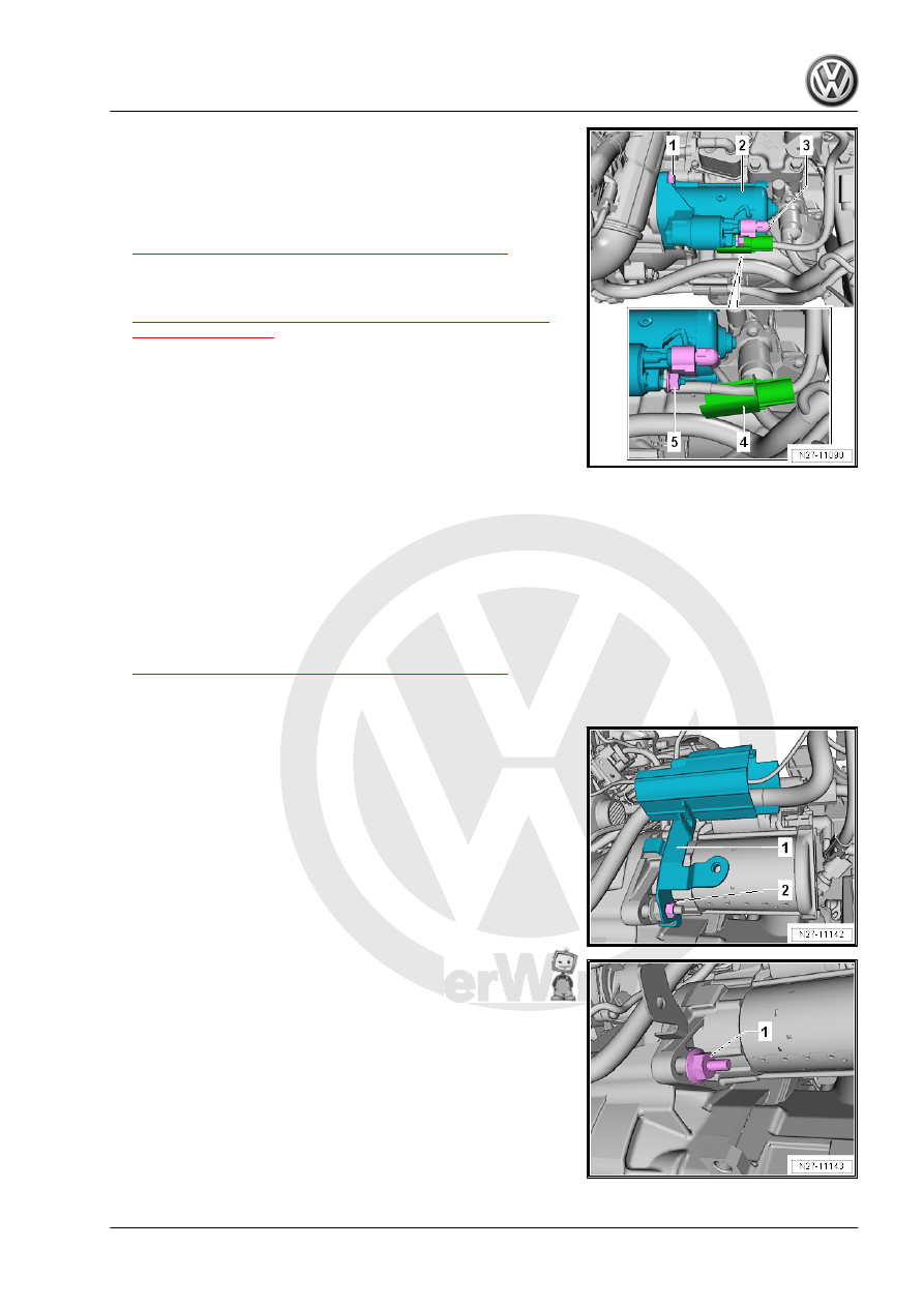
– Remove the nut -2-.
– Remove the bracket -1- for the wiring harness.
– Remove the bolt -1-.
– If necessary, remove the air filter housing. Refer to ⇒ Rep.
Gr. 24 ; Air Filter; Air Filter Housing, Removing and Installing .