Volkswagen Golf / Golf GTI / Jetta. Manual - part 570


  Index      Volkswagen     Volkswagen Golf / Golf GTI / Jetta - service repair manual 1999-2005 year


Search            copyright infringement  


Content   ..  568  569  570  571   ..


Volkswagen Golf / Golf GTI / Jetta. Manual - part 570


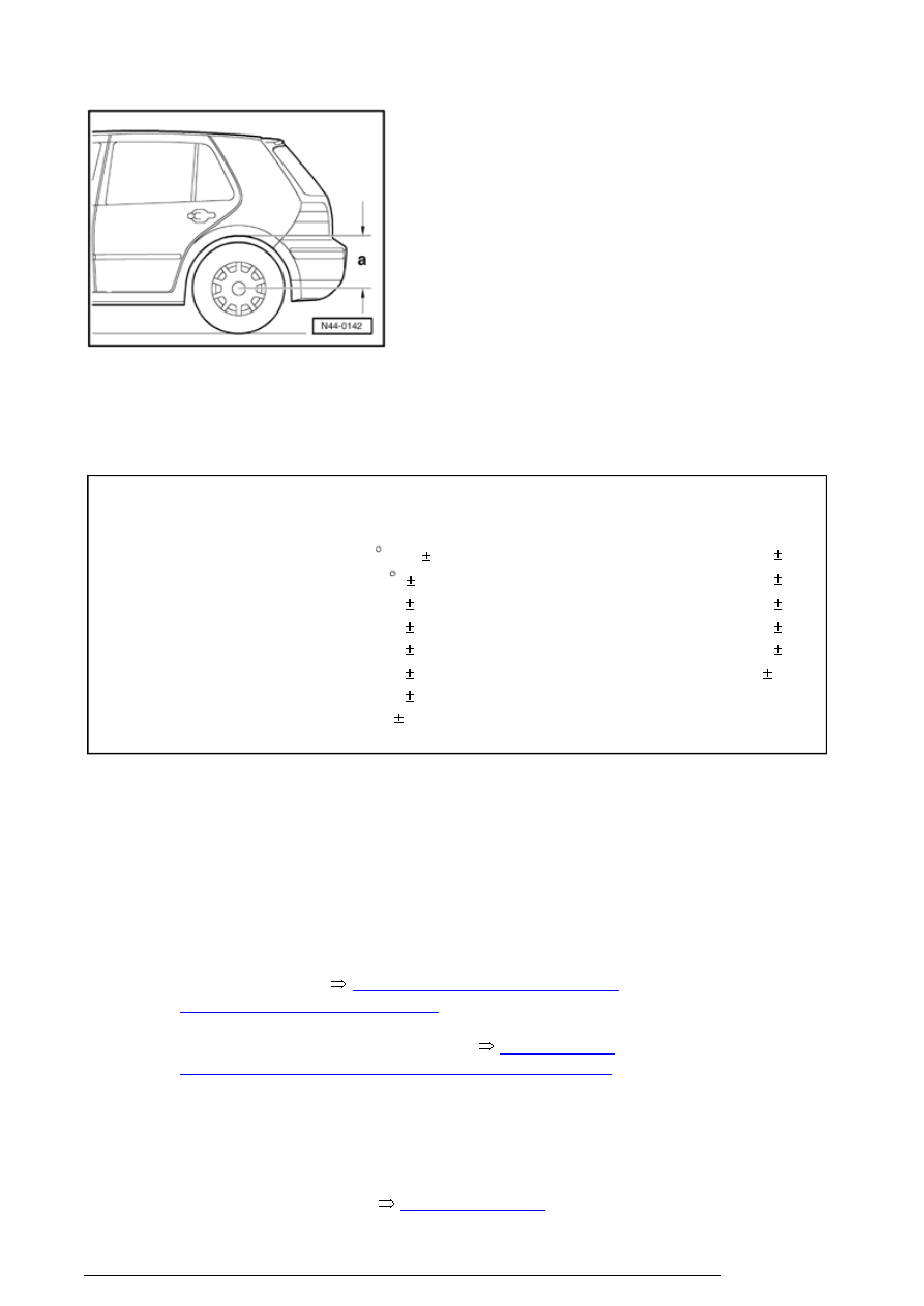
- Measure dimension - a - from center of wheel to lower 
edge of wheelhousing. 

Specifications for camber 

Golf, Jetta, Jetta Wagon with  

basic or sport suspension 

Golf, Jetta, Jetta Wagon with  

heavy duty suspension 

Ride height dimension "a" 

Camber

Ride height dimension "a" 

Camber

370 mm

-1   10’   20’ 

400 mm

-50’   20’ 

375 mm

-1     20’ 

405 mm

-40’   20’ 

380 mm

-50’   20’ 

410 mm

-30’   20’ 

385 mm

-40’   20’ 

415 mm

-20’   20’ 

390 mm

-30’   20’ 

420 mm

-10’   20’ 

395 mm

-20’   20’ 

425 mm

0   20’ 

400 mm

-10’   20’ 


405 mm

0   20’ 


Max. allowable difference between left and right max. 20 ’

Overview of work procedure for measuring 
vehicle


The following work sequence must be adhered to!

1 - Check front axle camber and adjust if necessary  

2 - Check rear axle camber.  

n

Vehicles with front wheel drive: Camber is not 
adjustable, Notes 


44-5, Camber on rear axle (front 

wheel drive vehicles), adjusting


n

Vehicles with all-wheel drive: Notes 


44-5, Camber 

on rear axle (vehicles with all-wheel drive), adjusting


3 - Check rear axle toe and adjust if necessary. 

Vehicles with front wheel drive

The rear axle toe is not adjustable. 


44-5, Toe on rear 

Wheel alignment


axle (front wheel drive vehicles), adjusting


Vehicles with all-wheel drive

Toe is adjustable. Adjusting toe, 


44-5, Toe on rear axle 

(vehicles with all-wheel drive), adjusting


4 - Check front axle toe angle and adjust if necessary;  

5 - Check which suspension is installed in vehicle. This 
information is found on the vehicle data sticker,   

Front axle camber, adjusting


If a value lies outside the tolerances, check trim height and 
balance if necessary 


44-5, Vehicle trim height Zero 

position

 . 

By moving the subframe is it possible to change the camber 
slightly.

- Loosen bolts - 1 - and - 2 - 

- Move subframe to equalize camber on both sides.  

Check caster; caster can also change when moving 
subframe. 

Check caster angle afterward. 

Wheel alignment


- Secure subframe with new bolts. 

Fastener/location 

Tightening torques

Subframe to body  
Bolt position - 1 -  
Use new bolts! 

100 Nm plus an additional 

1

 / 

4

 turn 90   

Subframe to body  
Bolt position - 2 -  
Use new bolts! 

100 Nm plus an additional 

1

 / 

4

 turn 90   

Camber on rear axle (front wheel drive 
vehicles), adjusting


Camber cannot be adjusted.

If a value lies outside the tolerances, check trim height and 
balance if necessary 


44-5, Vehicle trim height Zero 

position

 . 

If the measured values are outside the permitted tolerances 
the axle beam must be checked for damage and replaced if 
necessary.

Camber on rear axle (vehicles with all-wheel 
drive), adjusting


For vehicles before model year 2003 the camber cannot be 
adjusted.

If a value lies outside the tolerances, check trim height and 
balance if necessary 


44-5, Vehicle trim height Zero 

position

 . 

If measured values are outside permitted tolerances the 
axle beam must be checked for damage and replaced if 
necessary.

From model year 2003 the camber is adjustable. The 
transverse link has only one hole. Here the camber can be 
adjusted too.

If a vehicle before model year 2003 has a transverse link 
with a hole, then the camber can be adjusted here too.

Wheel alignment


- Loosen bolts - 1 - and - 2 - for transverse link. 

3 - Upper transverse link 

4 - Lower transverse link  

5 - Trailing arm  

- Press wheel in and out to adjust to prescribed value. 

- Tighten bolted connection transverse link/trailing arm with 
70 Nm. 

- Check camber adjustment. If necessary, repeat 
adjustment. 

- If adjustment is o.k., tighten bolted connection transverse 
link/trailing arm with an additional 1/4 turn 90   . 

Toe on rear axle (front wheel drive vehicles), 
adjusting


If a value lies outside the tolerances, check trim height and 
balance if necessary 


44-5, Vehicle trim height Zero 

position

 . 

The total toe for the rear axle is not adjustable.

Only by moving the mounting bracket is it possible to adjust 
the individual toe evenly.

If measured values are outside the allowable tolerances the 
axle beam must be checked for damage and replaced if 
necessary.

- Loosen all bolts on mounting brackets - 1 - 

Wheel alignment


Content   ..  568  569  570  571   ..